MC33153
10
8.0
6.0
4.0
2.0
0
10
Output High
Output Low
8.0
6.0
4.0
2.0
0
T = 25°C
A
V
V
= 15 V
CC
= V
Pin 4
CC
Drive Output Open
5.0
10
15
20
−60 −40 −20
0
20
40
60
80 100 120 140
V
, SUPPLY VOLTAGE (V)
CC
T , AMBIENT TEMPERATURE (°C)
A
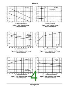
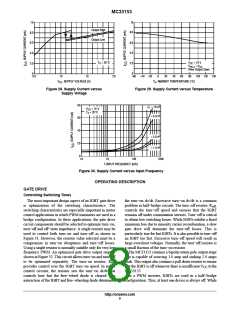
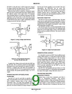
Figure 28. Supply Current versus
Supply Voltage
Figure 29. Supply Current versus Temperature
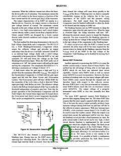
80
C = 10 nF
L
V
= 15 V
CC
T = 25°C
A
= 5.0 nF
60
40
20
0
= 2.0 nF
= 1.0 nF
1.0
10
100
1000
f, INPUT FREQUENCY (kHz)
Figure 30. Supply Current versus Input Frequency
OPERATING DESCRIPTION
GATE DRIVE
Controlling Switching Times
The most important design aspect of an IGBT gate drive
is optimization of the switching characteristics. The
switching characteristics are especially important in motor
control applications in which PWM transistors are used in a
bridge configuration. In these applications, the gate drive
circuit components should be selected to optimize turn−on,
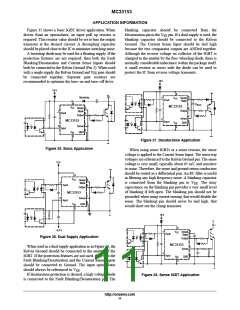
turn−off and off−state impedance. A single resistor may be
used to control both turn−on and turn−off as shown in
Figure 31. However, the resistor value selected must be a
compromise in turn−on abruptness and turn−off losses.
Using a single resistor is normally suitable only for very low
frequency PWM. An optimized gate drive output stage is
shown in Figure 32. This circuit allows turn−on and turn−off
the turn−on dv/dt. Excessive turn−on dv/dt is a common
problem in half−bridge circuits. The turn−off resistor, R
,
off
controls the turn−off speed and ensures that the IGBT
remains off under commutation stresses. Turn−off is critical
to obtain low switching losses. While IGBTs exhibit a fixed
minimum loss due to minority carrier recombination, a slow
gate drive will dominate the turn−off losses. This is
particularly true for fast IGBTs. It is also possible to turn−off
an IGBT too fast. Excessive turn−off speed will result in
large overshoot voltages. Normally, the turn−off resistor is
a small fraction of the turn−on resistor.
The MC33153 contains a bipolar totem pole output stage
that is capable of sourcing 1.0 amp and sinking 2.0 amps
peak. This output also contains a pull down resistor to ensure
to be optimized separately. The turn−on resistor, R ,
on
provides control over the IGBT turn−on speed. In motor
control circuits, the resistor sets the turn−on di/dt that
controls how fast the free−wheel diode is cleared. The
interaction of the IGBT and free−wheeling diode determines
that the IGBT is off whenever there is insufficient V to the
MC33153.
In a PWM inverter, IGBTs are used in a half−bridge
configuration. Thus, at least one device is always off. While
CC
http://onsemi.com
8

 ONSEMI [ ONSEMI ]