AC Loadings and Waveforms
A
nB1
nB2
10pF
50Ω
GND
+
VB
Control
S OE
–
GND
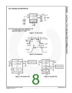
Notes: Input driven by 50Ω source terminated in 50Ω.
CL includes load and stray capacitance.
Input PRR-1.0MHz, tW = 500ns.
Figure 9. AC Test Circuit
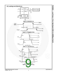
tr = 2.5ns
90% 90%
1.5V 1.5V
tf = 2.5ns
3.0V
SELECT
INPUT
10%
tON
10%
tOFF
GND
VOH
90%
90%
OUTPUT
VOL
Figure 10. AC Waveforms
B1
B1
A
A
Network Analyzer
100Ω
100Ω
50Ω
50Ω
B2
Network Analyzer
50Ω
S
Control
S
Control
OE
OE
Figure 11. Off Isolation Test
Figure 12. Crosstalk Test
© 2005 Fairchild Semiconductor Corporation
FSUSB20 • Rev. 1.0.3
www.fairchildsemi.com
7

 ONSEMI [ ONSEMI ]