AC Electrical Characteristics
Typical values are at VCC = 3.3V and TA = 25°C.
Symbol
Parameter
Condition
VCC(V)
Typ.
Max.
Unit
Figure
Turn-On Time
S-to-Bus B
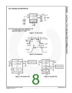
Figure 9
Figure 10
tON
VB = 0.8V
3.0 to 3.6
4.8
7.0
ns
Turn-Off Time
S-to-Bus B
Figure 9
Figure 10
tOFF
VB = 0.8V
CL = 10pF
3.0 to 3.6
2.2
4.0
ns
tPD
Propagation Delay
3.0 to 3.6
3.0 to 3.6
0.25
-26
ns
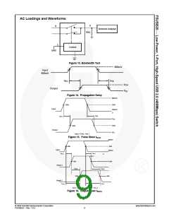
Figure 14
Figure 11
f = 250MHz,
RL = 50Ω
Non-Adjacent Off
Isolation
OIRR
dB
f = 250MHz,
RL = 50Ω
Non-Adjacent
Channel Crosstalk
XTALK
BW
3.0 to 3.6
3.0 to 3.6
-45
dB
Figure 12
Figure 13
750
435
RL = 50Ω, CL = 0pF
RL = 50Ω, CL = 5pF
-3dB Bandwidth
MHz
USB Related AC Electrical Characteristics
Typical values are at VCC = 3.3V and TA = 25°C.
Symbol
Parameter
Condition
VCC (V)
Typ.
Unit
Figure
Channel-to Channel
Skew
Figure 14
Figure 16
tSK(O)
CL = 10pF
3.0 to 3.6
3.0 to 3.6
3.0 to 3.6
0.051
ns
Skew of Opposite
Transition of the
Same Output
Figure 14
Figure 16
tSK(P)
CL = 10pF
0.020
0.170
ns
ns
RL = 50Ω, CL = 10pF
tR = tF = 750ps at 480MPs
TJ
Total Jitter
Capacitance
Typical values are at VCC = 3.3V and TA = 25°C.
Symbol
CIN
Parameter
Control Pin Input Capacitance
A/B On Capacitance
Condition
Typ.
Unit
pF
VCC = 0V
2.5
12.0
4.5
CON
VCC = 3.3V, /OE = 0V
VCC and /OE = 3.3V
pF
COFF
Port B Off Capacitance
pF
© 2005 Fairchild Semiconductor Corporation
FSUSB20 • Rev. 1.0.3
www.fairchildsemi.com
5

 ONSEMI [ ONSEMI ]