Electrical Characteristics TJ = 25 °C unless otherwise noted
Symbol
Parameter
Test Conditions
Min
Typ
Max
Units
Off Characteristics
BVDSS
Drain to Source Breakdown Voltage
ID = 250 μA, VGS = 0 V
100
V
ΔBVDSS
ΔTJ
Breakdown Voltage Temperature
Coefficient
I
D = 250 μA, referenced to 25 °C
67
mV/°C
IDSS
IGSS
Zero Gate Voltage Drain Current
Gate to Source Leakage Current
VDS = 80 V, VGS = 0 V
VGS = ±20 V, VDS = 0 V
1
μA
±100
nA
On Characteristics (Note 2)
VGS(th)
Gate to Source Threshold Voltage
VGS = VDS, ID = 250 μA
2
3.1
4
V
ΔVGS(th)
ΔTJ
Gate to Source Threshold Voltage
Temperature Coefficient
I
D = 250 μA, referenced to 25 °C
-8.5
mV/°C
V
GS = 10 V, ID = 8 A
19
26
33
21
24
38
44
rDS(on)
gFS
Static Drain to Source On Resistance
Forward Transconductance
VGS = 6 V, ID = 6 A
mΩ
VGS = 10 V, ID = 8 A, TJ = 125 °C
VDS = 10 V, ID = 8 A
S
Dynamic Characteristics
Ciss
Coss
Crss
Rg
Input Capacitance
780
180
15
1035
240
25
pF
pF
pF
Ω
VDS = 50 V, VGS = 0 V,
f = 1 MHz
Output Capacitance
Reverse Transfer Capacitance
Gate Resistance
0.4
Switching Characteristics
td(on)
tr
td(off)
tf
Turn-On Delay Time
Rise Time
7.6
3
15
10
24
10
19
11
ns
ns
VDD = 50 V, ID = 8 A,
VGS = 10 V, RGEN = 6 Ω
Turn-Off Delay Time
Fall Time
13.4
2.9
13.4
7.6
4.0
3.7
ns
ns
Qg
Total Gate Charge
Total Gate Charge
Gate to Source Gate Charge
Gate to Drain “Miller” Charge
VGS = 0 V to 10 V
nC
nC
nC
nC
Qg
VGS = 0 V to 5 V
VDD = 50 V,
ID = 8 A
Qgs
Qgd
Drain-Source Diode Characteristics
V
GS = 0 V, IS = 8 A
(Note 2)
(Note 2)
0.8
0.7
43
1.3
1.2
68
VSD
Source to Drain Diode Forward Voltage
V
VGS = 0 V, IS = 2.6 A
trr
Reverse Recovery Time
ns
IF = 8 A, di/dt = 100 A/μs
Qrr
Reverse Recovery Charge
43
68
nC
Notes:
1. R
R
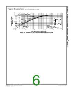
is the sum of the junction-to-case and case-to-ambient thermal resistance where the case thermal reference is defined as the solder mounting surface of the drain pins.
θJA
θJC
is guaranteed by design while R
is determined by the user’s board design.
θJA
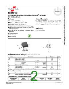
a. 40 °C/W when mounted on a
b. 96 °C/W when mounted on a
minimum pad of 2 oz copper.
2
1 in pad of 2 oz copper.
2. Pulse Test: Pulse Width < 300 μs, Duty cycle < 2.0%.
3. E 121 mJ is based on starting T = 25 °C, L = 3 mH, I = 9 A, V = 100 V, V = 10 V. 100% test at L = 0.1 mH, I = 30 A.
AS
J
AS
DD
GS
AS
4. Pulsed Drain current is tested at 300 μs with 2% duty cycle. For repetitive pulses, the pulse width is limited by the maximum junction temperature.
2
www.fairchildsemi.com
©2012 Fairchild Semiconductor Corporation
FDD86102 Rev.1.9

 ONSEMI [ ONSEMI ]