CAT1021, CAT1022, CAT1023
Table 9. RESET CIRCUIT AC CHARACTERISTICS
Symbol
Parameter
Test Conditions
Note 2
Min
Typ
Max
270
5
Units
ms
ms
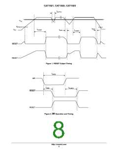
t
Power−Up Reset Timeout
130
200
PURST
t
V
TH
V
CC
to RESET output Delay
Glitch Reject Pulse Width
Note 3
RDP
t
Notes 4 and 5
Note 1
30
ns
GLITCH
MR Glitch
Manual Reset Glitch Immunity
MR Pulse Width
100
ns
t
Note 1
5
ms
MRW
t
MR Input to RESET Output Delay
Watchdog Timeout
Note 1
1
ms
MRD
t
Note 1
1.0
1.6
2.1
sec
WD
Table 10. POWER−UP TIMING (Notes 5 and 6)
Symbol
Parameter
Power−Up to Read Operation
Power−Up to Write Operation
Test Conditions
Min
Typ
Max
270
270
Units
ms
t
PUR
t
ms
PUW
Table 11. AC TEST CONDITIONS
Parameter
Test Conditions
Input Pulse Voltages
0.2 x V to 0.8 x V
CC
CC
Input Rise and Fall Times
Input Reference Voltages
Output Reference Voltages
Output Load
10 ns
0.3 x V , 0.7 x V
CC
CC
0.5 x V
CC
Current Source: I = 3 mA; C = 100 pF
OL
L
Table 12. RELIABILITY CHARACTERISTICS
Symbol
(Note 5)
Parameter
Endurance
Reference Test Method
Min
1,000,000
100
Max
Units
N
MIL−STD−883, Test Method 1033
MIL−STD−883, Test Method 1008
MIL−STD−883, Test Method 3015
JEDEC Standard 17
Cycles/Byte
Years
END
T
(Note 5)
(Note 5)
Data Retention
DR
V
ESD Susceptibility
2000
Volts
ZAP
I
(Notes 5 & 7) Latch−Up
100
mA
LTH
1. Test Conditions according to “AC Test Conditions” table.
2. Power−up, Input Reference Voltage V = V , Reset Output Reference Voltage and Load according to “AC Test Conditions” Table
CC
TH
3. Power−Down, Input Reference Voltage V = V , Reset Output Reference Voltage and Load according to “AC Test Conditions” Table
CC
TH
4. V Glitch Reference Voltage = V
; Based on characterization data
CC
THmin
5. This parameter is characterized initially and after a design or process change that affects the parameter. Not 100% tested.
6. t
and t
are the delays required from the time V is stable until the specified memory operation can be initiated.
PUR
PUW CC
7. Latch−up protection is provided for stresses up to 100 mA on input and output pins from −1 V to V + 1 V.
CC
http://onsemi.com
6

 ONSEMI [ ONSEMI ]