G6B
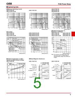
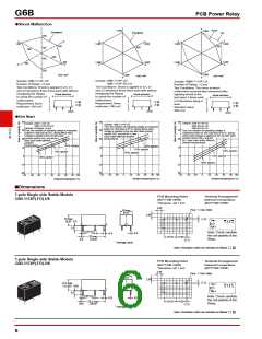
●Shock Malfunction
PCB Power Relay
Y
Y
Y
Reset
1,000
1,000
Energized
Energized
Set
300
X
400
Z
X
1,000
X
1,000
Z
Z
1,000
1,000
300
700
600
100
100
200
200
400
X'
1,000
X'
1,000
Z'
1,000
Z'
1,000
X'
300
Z'
300
Unit: m/s2
1,000
Y'
1,000
Y'
Unit: m/s2
Unit: m/s2
Y'
Sample: G6B-1174P-US
G6B-1174P-FD-US
Test Conditions: Shock is applied in ±X, ±Y,
and ±Z directions three times each with without
Sample: G6B-1114P-US
Number of Relays: 12 pcs
Test Conditions: Shock is applied in ±X, ±Y,
and ±Z directions three times each with without
Sample: G6BK-1114P-US
Number of Relays: 12 pcs
Test Conditions: The value at which
malfunction occurred was measured after
applying shock to the
energizing the Relays
to check the number of
malfunctions.
energizing the Relays
Shock direction
Shock direction
Shock direction
X
X'
X
X'
to check the number of
malfunctions.
X
X'
test piece 3 times each
in 6 directions along 3
Y
Y
Y
Z
Z
Z
Requirement: None
Requirement: None
axes.
Z'
Z'
malfuction 100 m/s2
malfuction 100 m/s2
Z'
Standard value:
300 m/s2
Y'
Y'
(Coil)
Y'
(Coil)
(Coil)
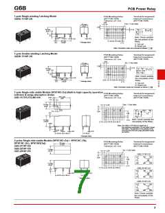
●Hot Start
40
40
40
30
Sample: G6B-2114P-US
G6B-2214P-US
G6B-2014P-US
Test: the variation of operating voltage is
measured based on coil cold start at 23°C, during
which rated voltage is applied to the coil with rated
contact current (5A), and left
for 1 hour each under different
ambient temperatures.
Sample: G6B-1114P-US
G6B-1174P-FD-US
Number of Relays: 10 pcs
Test: the variation of operating voltage is measured
based on cold start at 23°C, during which rated
voltage is applied to the coil with rated
contact current (5A), and left for 1
hour each under different
Sample: G6B-1174P-US
Test: the variation of operating voltage is measured
based on cold start at 23°C, during which rated
voltage is applied to the coil with rated contact
current (8A), and left for 1 hour
G
6
B
30
20
10
0
30
each under different ambient
20 temperatures.
20
10
0
ambient
temperatures.
120% applied
110% applied
120% applied
110% applied
100% applied
10
0
120% applied
110% applied
100% applied
100% applied
−10
−10
−20
−10
−20
−20
−50
−40 −20
0
20
40
60
80 100
−50
−40 −20
0
20
40
60
80 100
−50
−40 −20
0
20
40
60
80 100
Ambient temperature (°C)
Ambient temperature (°C)
Ambient temperature (°C)
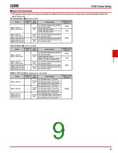
■Dimensions
1-pole Single-side Stable Models
G6B-1114P(-FD)-US
PCB Mounting Holes
(BOTTOM VIEW)
Tolerance: ±0.1 mm
Terminal Arrangement/
Internal Connections
(BOTTOM VIEW)
2.54
Four, 1.1-dia. holes
10 max.
(9.8)*
2.54
10 max.
(9.8)* 0.3
(1.2)
1
3
4
6
3.5
0.85 0.9
Note: Check carefully
the coil polarity of the
Relay.
0.5
0.9
20 max.
(19.9)*
10.16
7.62
0.5
(1.1)
* Average value
Note: Orientation marks are indicated as follows:
1-pole Single-side Stable Models
G6B-1174P(-FD)-US
PCB Mounting Holes
(BOTTOM VIEW)
Tolerance: ±0.1 mm
2.54
Terminal Arrangement/
Internal Connections
(BOTTOM VIEW)
Four, 1.1-dia. holes
10 max.
(9.9)*
2.54
(1.2)
12.5 max.
(12.45)* 0.65
1
6
3
4
3.5
0.85 0.9
Note: Check carefully
the coil polarity of the
Relay.
0.5
0.9
20.2 max.
(20.0)*
10.16
7.62
0.45
(1.2)
* Average value
Note: Orientation marks are indicated as follows:
6

 OMRON [ OMRON ELECTRONICS LLC ]