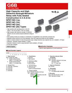
G6B
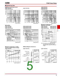
■Ratings
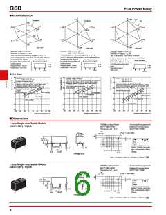
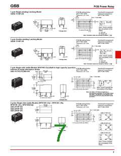
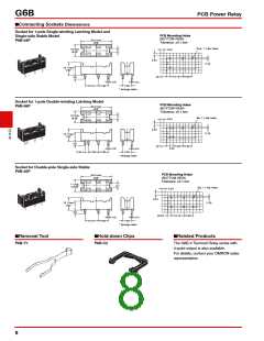
PCB Power Relay
●Coil: 1-Pole, Single-side Stable Type (Including models for ultrasonically cleanable)
Must operate Must release Max. voltage
Item
Rated current Coil resistance
Power consumption
(mW)
voltage (V)
voltage (V)
(V)
(mA)
(Ω)
Rated voltage
% of rated voltage
5 VDC
6 VDC
40
125
180
33.3
16.7
8.3
160%
(at 23°C)
70% max.
10% min.
Approx. 200
12 VDC
24 VDC
720
2,880
●Coil: 2-Pole, Single-side Stable Type (Including models for ultrasonically cleanable)
Must operate Must release Max. voltage
Item
Rated current Coil resistance
Power consumption
(mW)
voltage (V)
voltage (V)
(V)
(mA)
(Ω)
Rated voltage
% of rated voltage
5 VDC
6 VDC
60
83.3
50
120
480
140%
(at 23°C)
80% max.
10% min.
Approx. 300
12 VDC
24 VDC
25
12.5
1,920
●Coil: Single-winding Latching Type (Including models for ultrasonically cleanable)
Must set Must reset Max. voltage
Item
Power consumption
Rated
current
(mA)
Coil
resistance
(Ω)
voltage (V) voltage (V)
(V)
Set coil
(mW)
Reset coil
(mW)
% of rated voltage
Rated voltage
5 VDC
6 VDC
40
125
180
G
6
B
33.3
16.7
8.3
160%
(at 23°C)
70% max. 70% max.
200
200
12 VDC
24 VDC
720
2,880
●Coil: Double-winding Latching Type (Including models for ultrasonically cleanable)
Must set voltage Must reset voltage Max. voltage
Rated current (mA)
Coil resistance (Ω)
Power consumption
Item
(V)
(V)
(V)
Set coil
(mW)
Reset coil
(mW)
Rated voltage
Set coil
Reset coil
Set coil Reset coil
% of rated voltage
5 VDC
6 VDC
56
56
89.2
128.5
515
89.2
128.5
515
46.8
23.3
11.7
46.8
23.3
11.7
130%
(at 23°C)
70% max.
70% max.
280
280
12 VDC
24 VDC
2,060
2,060
●Coil: Operation Indicator Model (Flux-resistant type. Do not wash down with water.)
Must operate Must release Max. voltage
Item
Rated current Coil resistance
Power consumption
(mW)
voltage (V)
voltage (V)
(V)
(mA)
(Ω)
Rated voltage
% of rated voltage
5 VDC
12 VDC
24 VDC
43
116
610
Approx. 200
Approx. 240
Approx. 275
130%
(at 23°C)
19.7
11.3
70% max.
10% min.
2,120
Note 1. The rated current and coil resistance are measured at a coil temperature of 23°C with a tolerance of ±10%.
2.The operating characteristics are measured at a coil temperature of 23°C.
3.The “Max. voltage” is the maximum voltage that can be applied to the relay coil.
●Contacts
G6B-1114P-US
G6BU-1114P-US
G6BK-1114P-US
G6B-1114P-FD-US
G6BU-1114P-FD-US
G6BK-1114P-FD-US
G6B-2114P-US
G6B-2214P-US
G6B-2014P-US
G6B-2114P-FD-US
G6B-2214P-FD-US
G6B-2014P-FD-US
G6B-1174P-US
G6B-1177P-ND-US
G6B-1174P-FD-US
G6B-1177P-FD-ND-US
Model
Load
Inductive load
= 0.4; L/R = 7 ms)
Inductive load
= 0.4; L/R = 7 ms)
Inductive load
(cosφ = 0.4; L/R = 7 ms)
Resistive load
Resistive load
Resistive load
Item
(cosφ
(cos
φ
Contact type
Contact material
Single
Ag-Alloy (Cd free)
5 A (3 A) at 250 VAC
5 A (3 A) at 30 VDC
2 A (2 A) at 250 VAC
2 A (2 A) at 30 VDC
8 A (5 A) at 250 VAC
8 A (5 A) at 30 VDC
2 A (2 A) at 250 VAC
2 A (2 A) at 30 VDC
5 A (3 A) at 250 VAC 1.5 A (1.5 A) at 250 VAC
5 A (3 A) at 30 VDC 1.5 A (1.5 A) at 30 VDC
5 A (5 A)
Rated load
Rated carry current
5 A (5 A)
8 A (5 A)
Max. switching voltage
Max. switching current
380 VAC, 125 VDC
8 A (5 A)
5 A (5 A)
5 A (5 A)
Note 1. The values in the parentheses ( ) are for -FD models only.
2.Use the -FD type for inductive load and switching load which contact roughening is small.
3

 OMRON [ OMRON ELECTRONICS LLC ]