G6B
■Precautions
PCB Power Relay
●Please refer to “PCB Relays Common Precautions” for correct use.
Correct Use
●Mounting
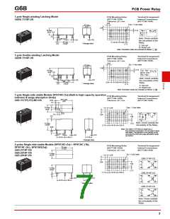
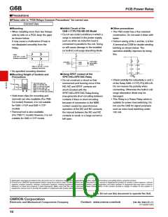
●Inhibit Circuit of the
●Other precautions
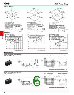
G6B-1177P(-FD)-ND-US Model
• When installing more than two Relays
side by side on a PCB, keep the gaps
as shown below0
• The P6B model has a flux-resistant
construction0 Do not wash it down with
water0
• Do not use under conditions in which a
surge is included in the power supply,
such as when an inductive load is
It may cause a malfunction if heat is
not dissipated smoothly from the
Relay0
• Perform wiring of No01 and No0 2 of the
X terminal as COM for double-winding
latching as shown below0 The
operation stability improves by doing
this0
connected in parallel to the coil0 Doing
so will cause damage to the installed
(or built-in) coil surge absorbing diode0
Pitch:
2.54 mm × 2 min.
between terminals
Coil surge
absorption
diode
Inductive
load
G6B
Coil
L
6
5
R
2
Pitch: 2.54 mm × 2 min.
between terminals
S
• No specified mounting direction0
1
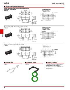
●Using SPDT contact of the
SPST-NO+SPST-NC Relay
●Mounting Height of Sockets and
COM
Precautions
• Check carefully the coil polarity (+ and -)
of the Relay G6B-1177P(-FD)-ND-US0
Do not reverse the polarity when
connecting0 Otherwise the built-in coil
surge absorption diode may be
damaged0
• Do not construct a circuit so that
overcurrent and burning occur if the
NO, NC and SPDT contacts are
short-circuited with the
G
6
B
* 19.5 mm max. for
*17 mm max.
G6B-1174P-FD-US,
G6B-1174P-US models
7 mm max.
and 22 mm max. for
G6B-1177P-FD-ND-US,
G6B-1177P-ND-US models.
SPST-NO+SPST-NC Relay0Arcing
may generate short-circuiting between
contacts if there is short-circuiting
because of conversion to the MBB
contact caused by asynchronous
operation of the NO and NC contacts,
the interval between the NO and NC
contacts is small, or a large current is
left open0
• Hold-down clips (for mounting and
removal) are also available0(For P6B-
C2 model) However, it is not suitable
for G6B-1174P and G6B-1177P
models0
• This Relay is a Power Relay which is
suitable for power load switching0 Do
not use the G6B for signal purposes
such as micro load switching under
1±± mA0
• Removal tool is also available0
(For P6B-Y1 model) However, it is not
suitable for G6B-1177P model0
• Application examples provided in this document are for reference only0 In actual applications, confirm equipment functions and safety before using the product0
• Consult your OMRON representative before using the product under conditions which are not described in the manual or applying the product to nuclear control systems, railroad
systems, aviation systems, vehicles, combustion systems, medical equipment, amusement machines, safety equipment, and other systems or equipment that may have a serious
influence on lives and property if used improperly0 Make sure that the ratings and performance characteristics of the product provide a margin of safety for the system or
equipment, and be sure to provide the system or equipment with double safety mechanisms0
Note: Do not use this document to operate the Unit.
OMRON Corporation
Electronic and Mechanical Components Company
Contact: www.omron.com/ecb
Cat. No. K021-E1-11
±714(±2±7)(O)
10

 OMRON [ OMRON ELECTRONICS LLC ]