G6B
■Engineering Data
PCB Power Relay
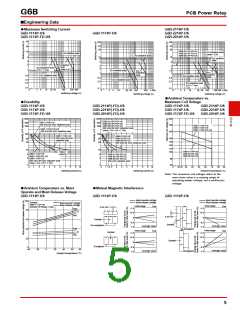
●Maximum Switching Current
G6B-1114P-US
G6B-1174P-FD-US
40
G6B-2114P-US
G6B-2214P-US
G6B-2014P-US
G6B-1174P-US
100
100
50
30
50
30
20
10
G6B-2114P-FD-US
G6B-2214P-FD-US
G6B-2014P-FD-US
AC inductive load
(cosφ = 0.4)
AC resistive load
AC resistive load
5
10
8
10
AC resistive
load
3
2
5
5
3
AC
inductive
load
cosφ = 0.4
3
2
DC inductive load
(L/R = 7 ms)
2
1.5
1
1
DC resistive load
AC
inductive
load
AC
1
resistive
load
DC resistive load
0.5
DC resistive load
0.5
0.3
0.5
0.3
0.3
0.2
DC inductive load
DC inductive load
(L/R = 7 ms)
0.1
0.1
0.1
0
3
5
10 20 30
100
300 500
0
3
5
10
30 50 100
380 1,000
0
3
5
10
30 50 100
300 500 1,000
Switching voltage (V)
Switching voltage (V)
Switching voltage (V)
●Ambient Temperature vs.
●Durability
Maximum Coil Voltage
G6B-1114P-US
G6B-1174P-US
G6B-1174P-FD-US
G6B-2114P(-FD)-US
G6B-2214P(-FD)-US
G6B-2014P(-FD)-US
G6B-1114P-US
G6B-1174P-US
G6B-1174P-FD-US
G6B-2114P-US
G6B-2214P-US
G6B-2014P-US
1,000
1,000
200
G
6
B
G6B-2114P(-FD)-US
500
G6B-1114P-US
250 VAC/30 VDC resistive load
500
300
G6B-2214P(-FD)-US
G6B-2014P(-FD)-US
250 VAC/30 VDC inductive load
(cosφ = 0.4, L/R = 7 ms)
180
G6B-1114P-US
G6B-1174P-US
G6B-1174P-FD-US
300
G6B-1174P-FD-US
250 VAC/30 VDC resistive load
160
100
100
G6B-1174P-US
250 VAC/30 VDC
resistive load
G6B-2114P-US
G6B-2214P-US
G6B-2014P-US
140
130
120
110
100
50
30
50
30
250 VAC/30 VDC resistive load
10
10
G6B-2114P-US
G6B-2214P-US
G6B-2014P-US
Higher
capacity
G6B-1114P-US
G6B-1174P-FD-US
G6B-1174P-US
G6B-2114P-FD-US
G6B-2214P-FD-US
G6B-2014P-FD-US
250 VAC resistive load
5
3
5
3
80
60
250 VAC/30 VDC inductive load
(cosφ = 0.4, L/R = 7 ms)
1
1
0
1
2
3
4
5
6
7
8
9
10
0
1 1.5 2
3
4
5
6
7
8
9
10
0
20 23 30
40
50
60
70
80 90
Switching current (A)
Switching current (A)
Ambient temperature (°C)
Note: The maximum coil voltage refers to the
maxi-mum value in a varying range of
operating power voltage, not a continuous
voltage.
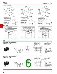
●Ambient Temperature vs. Must
Operate and Must Release Voltage
G6B-1114P-US
●Mutual Magnetic Interference
G6B-1114P-US
G6B-1114P-US
Must operate voltage
Must release voltage
Must operate voltage
Must release voltage
100
Sample:
G6B-1114P-US
Number of Relays: 5 pcs
Must operate voltage
Must release voltage
Initial stage
Test
Initial stage
Test
2.54 mm
+1.0
+1.0
max.
80
60
40
20
X
+0.5
+0.5
min.
2.54 mm
0
0
Sample
De-energized
−0.5
−1.0
−0.5
Sample
Average value
Average value
−1.0
max.
De-energized
Initial stage
Initial stage
Test
Test
Sample
X
+1.0
+1.0
min.
+0.5
+0.5
Sample
0
0
Energized
−0.5
−1.0
−0.5
−1.0
0
−40
−20
0
20
40
60
80
Average value
Average value
Energized
Ambient temperature (°C)
5

 OMRON [ OMRON ELECTRONICS LLC ]