CJ2M-CPU3@/-CPU1@/-MD21@
Performance Specifications
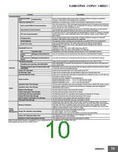
CJ2M-
CPU13/33
20K steps
Items
CPU11/31
5K steps
CPU12/32
10K steps
CPU14/34
30K steps
CPU15/35
60K steps
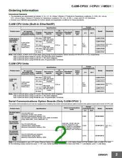
User Memory
I/O Bits
2,560 bits
Normal Mode:
CJ2M-CPU3@: 270 μs
CJ2M-CPU1@: 160 μs
Overhead Processing Time *1
Basic Instructions : 0.04 μs min.
Special Instructions : 0.06 μs min.
Interrupt task startup time: 31 μs
Return time to cyclic task : 10 μs
Execution Time
Processing
Speed
I/O Interrupts and
External Interrupts
Interrupts
Minimum time interval : 0.4 ms (set in 0.1 ms increments)
Interrupt task startup time: 30 μs
Return time to cyclic task : 11 μs
Scheduled
Interrupts
Total per CPU Rack or Expansion Rack: 10 Units max.;
Total per PLC: 40 Units max.
No limit
Maximum Number of Connectable Units
Basic I/O Units
However, a maximum of two CJ1W-INT01 Interrupt Input Units can be mounted.
Units for up to 96 unit numbers can be mounted. (Unit numbers run from 0 to 95. Units are allocated between
1 and 8 unit numbers.)
Special I/O Units
CJ2M-CPU3@: 15 Units max.
CJ2M-CPU1@: 16 Units max.
CPU Bus Units
2 Units max. *
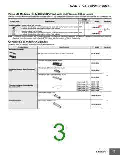
Pulse I/O Modules
* Supported only by CJ2M CPU Units with unit version 2.0 or later. A Pulse I/O Module must be mounted.
Slots for which interrupts can be
Slots 0 to 4 on CPU Rack
used
Maximum Number of Expansion Racks
I/O Area
3 max.
2,560 bits (160 words) : Words CIO 0000 to CIO 0159
3,200 bits (200 words) : Words CIO 1000 to CIO 1199
6,400 bits (400 words) : Words CIO 1500 to CIO 1899
15,360 bits (960 words): Words CIO 2000 to CIO 2959
20 inputs, 12 outputs (CIO 2960 to CIO 2963)
1,440 bits (90 words) : Words CIO 3100 to CIO 3189
9,600 bits (600 words) : Words CIO 3200 to CIO 3799
Link Area
CPU Bus Unit Area
Special I/O Unit Area
Pulse I/O Area
Serial PLC Link Words
DeviceNet Area
CIO Area
3,200 bits (200 words) : Words CIO 1300 to CIO 1499 (Cannot be used for external I/O.)
37,504 bits (2,344 words): Words CIO 3800 to CIO 6143 (Cannot be used for external I/O.)
Internal I/O Area
Work Area
8,192 bits (512 words): Words W000 to W511 (Cannot be used for external I/O.)
8,192 bits (512 words): Words H000 to H511
Bits in this area maintain their ON/OFF status when PLC is turned OFF or operating mode is changed.
Words H512 to H1535: These words can be used only for function blocks. They can be used only for function
block instances (i.e., they are allocated only for internal variables in function blocks).
Holding Area
Read-only: 31,744 bits (1,984 words)
• 7,168 bits (448 words): Words A0 to A447
• 24,576 bits (1,536 words): Words A10000 to A11535 *
Auxiliary Area
Read/write: 16,384 bits (1,024 words) in words A448 to A1471 *
* A960 to A1471 and A10000 to A11535 cannot be accessed by CPU Bus Units, Special I/O Units, PTs, and
Support Software that do not specifically support the CJ2 CPU Units.
Temporary Area
Timer Area
Counter Area
16 bits: TR0 to TR15
4,096 timer numbers (T0000 to T4095 (separate from counters))
4,096 counter numbers (C0000 to C4095 (separate from timers))
32k words *
• DM Area words for Special I/O Units: D20000 to D29599 (100 words × 96 Units)
• DM Area words for CPU Bus Units: D30000 to D31599 (100 words × 16 Units)
* Bits in the EM Area can be addressed either by bit or by word. These bits cannot be addressed by CPU Bus
Units, Special I/O Units, PTs, and Support Software that do not specifically support the CJ2 CPU Units.
32k words/bank × 4 banks max.: E00_00000 to E3_32767 max. *
* Bits in the EM Area can be addressed either by bit or by word. These bits cannot be addressed by CPU Bus
Units, Special I/O Units, PTs, and Support Software that do not specifically support the CJ2 CPU Units.
DM Area
EM Area
32K words × 1 bank
Bank 0 hex
32K words × 4 banks
Bank 0 to 3 hex
Force-S/R Enabled Banks *2
IR0 to IR15
Index Registers
These are special registers for storing PLC memory addresses for indirect addressing. (Index Registers can
be set so that they are unique in each task or so that they are shared by all tasks.)
Cyclic Task Flag Area
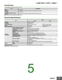
Memory Card
128 flags
128 MB, 256 MB, or 512 MB
PROGRAM Mode: Programs are not executed. Preparations can be executed prior to program execution in
this mode.
MONITOR Mode: Programs are executed, and some operations, such as online editing, and changes to
present values in I/O memory, are enabled in this mode.
Operating Modes
RUN Mode:
Programs are executed. This is the normal operating mode.
*1. The following time must be added when using EtherNet/IP tag data links for the CJ2M-CPU3@.
100 μs + (Number of words transferred × 1.8 μs)
The following time must be added when using Pulse I/O Modules with a CJ2M CPU Unit:
10 μs × Number of Pulse I/O Modules
*2. Force-setting/resetting bits in the EM Area is possible only for banks specified for the EM Area force-set/reset function.
6

 OMRON [ OMRON ELECTRONICS LLC ]