TJA1055
NXP Semiconductors
Enhanced fault-tolerant CAN transceiver
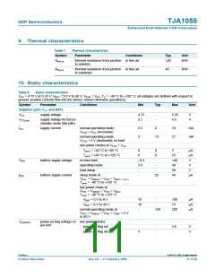
POWER-ON
STANDBY
10
GOTO
SLEEP
(4)
NORMAL
11
(5)
01
STANDBY
00
SLEEP
00
(1)
(2)
(3)
mbk949
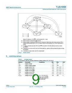
Mode 10 stands for: Pin STB = HIGH and pin EN = LOW.
(1) Mode change via input pins STB and EN.
(2) Mode change via input pins STB and EN; it should be noted that in the sleep mode pin INH is
inactive and possibly there is no VCC. Mode control is only possible if VCC of the transceiver is
active.
(3) Pin INH is activated and pins RXD and ERR are pulled LOW after wake-up via bus or input
pin WAKE.
(4) Transitions to normal mode clear the internal wake-up: wake-up interrupt flag and power-on flag
are cleared.
(5) Transitions to sleep mode: pin INH is deactivated.
Fig 3. Mode control
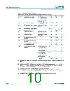
8. Limiting values
Table 6.
Limiting values
In accordance with the Absolute Maximum Rating System (IEC 60134).[1]
Symbol
VCC
Parameter
Conditions
Min
−0.3
−0.3
−0.3
−0.3
−0.3
−0.3
−0.3
−58
Max
Unit
V
supply voltage
+6
VBAT
battery supply voltage
voltage on pin TXD
voltage on pin RXD
voltage on pin ERR
voltage on pin STB
voltage on pin EN
voltage on pin CANH
+58
V
VTXD
VRXD
VERR
VSTB
VEN
VCC + 0.3
VCC + 0.3
VCC + 0.3
VCC + 0.3
VCC + 0.3
+58
V
V
V
V
V
VCANH
VCC = 0 V to 5.0 V;
V
VBAT ≥ 0 V; no time
limit; with respect to
any other pin
TJA1055_4
© NXP B.V. 2009. All rights reserved.
Product data sheet
Rev. 04 — 17 February 2009
9 of 26

 NXP [ NXP ]