TJA1055
NXP Semiconductors
Enhanced fault-tolerant CAN transceiver
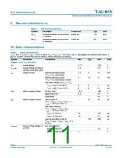
9. Thermal characteristics
Table 7.
Symbol
Rth(j-a)
Thermal characteristics
Parameter
Conditions
Typ
Unit
thermal resistance from junction in free air
to ambient
120
K/W
Rth(j-s)
thermal resistance from junction in free air
to substrate
40
K/W
10. Static characteristics
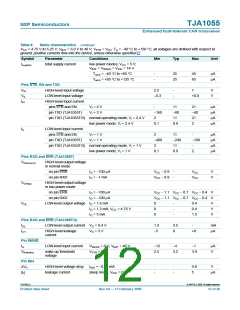
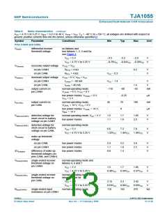
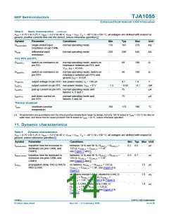
Table 8.
Static characteristics
VCC = 4.75 V to 5.25 V; VBAT = 5.0 V to 40 V; VSTB = VCC; Tvj = −40 °C to +150 °C; all voltages are defined with respect to
ground; positive currents flow into the device; unless otherwise specified.[1]
Symbol
Parameter
Conditions
Min
Typ
Max
Unit
Supplies (pins VCC and BAT)
VCC
supply voltage
4.75
3.1
-
-
5.25
4.5
V
V
VCC(stb)
supply voltage for forced
standby mode (fail-safe)
ICC
supply current
normal operating mode;
2.5
3
6
10
21
mA
mA
VTXD = VCC (recessive)
normal operating mode;
13
VTXD = 0 V (dominant); no load
low power modes at VTXD = VCC
Tamb = −40 °C to +85 °C
Tamb = +85 °C to +125 °C
no time limit
0
0
0
-
5
µA
µA
V
0
25
+40
40
58
40
VBAT
battery supply voltage
battery supply current
−0.3
operating mode
5.0
-
V
load dump
-
-
-
V
IBAT
sleep mode at
25
µA
V
RTL = VWAKE = VINH = VBAT = 14 V
;
T
amb = −40 °C to +125 °C
low power mode at
VRTL = VWAKE = VINH = VBAT
;
T
amb = −40 °C to +125 °C
VBAT = 5 V to 8 V
10
10
-
-
100
75
µA
µA
µA
VBAT = 8 V to 40 V
-
normal operating mode at
150
220
VRTL = VWAKE = VINH = VBAT = 5 V
to 40 V
Vpof(BAT)
power-on flag voltage on low power modes
pin BAT
power-on flag set
-
-
-
3.8
-
V
V
power-on flag not set
5
TJA1055_4
© NXP B.V. 2009. All rights reserved.
Product data sheet
Rev. 04 — 17 February 2009
11 of 26

 NXP [ NXP ]