TJA1055
NXP Semiconductors
Enhanced fault-tolerant CAN transceiver
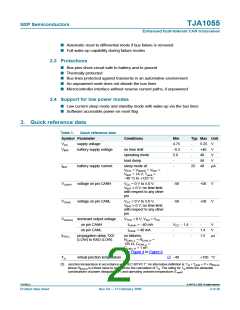
Table 4.
Bus failures
Failure Description
Termination Termination CANH
CANH (RTH) CANL (RTL) driver
CANL
driver
Receiver
mode
1
CANH wire
interrupted
on
on
on
on
differential
2
3
CANL wire interrupted on
CANH short-circuited weak[1]
to battery
on
on
on
off
on
on
differential
CANL
3a
4
CANH short-circuited weak[1]
to VCC
on
off
on
on
on
on
on
on
off
on
off
on
off
CANL
CANL short-circuited on
to ground
weak[2]
on
CANH
5
CANH short-circuited on
to ground
differential
CANH
6
CANL short-circuited on
to battery
weak[2]
on
6a
7
CANL short-circuited on
to VCC
differential
CANH
CANL and CANH
mutually
on
weak[2]
short-circuited
[1] A weak termination implies a pull-down current source behavior of 75 µA typical.
[2] A weak termination implies a pull-up current source behavior of 75 µA typical.
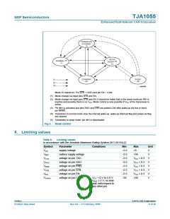
Failure 6 is detected if the CANL bus line exceeds its comparator threshold for a certain
period of time. This delay is needed to avoid false triggering by external RF fields. After
detection of failure 6, the reception is switched to the single-wire mode through CANH; the
CANL driver is switched off and the RTL bias changes to the pull-up current source.
Recovery from failures 3, 3a and 6 is detected automatically after reading a consecutive
recessive level by corresponding comparators for a certain period of time.
Failures 4 and 7 initially result in a permanent dominant level on pin RXD. After a time-out
the CANL driver is switched off and the RTL bias changes to the pull-up current source.
Reception continues by switching to the single-wire mode via pins CANH or CANL. When
failures 4 or 7 are removed, the recessive bus levels are restored. If the differential voltage
remains below the recessive threshold level for a certain period of time, reception and
transmission switch back to the differential mode.
If any of the wiring failure occurs, the output signal on pin ERR will be set to LOW. On
error recovery, the output signal on pin ERR will be set to HIGH again. In case of an
interrupted open bus wire, this failure will be detected and signalled only if there is an
open wire between the transmitting and receiving node(s). Thus, during open wire
failures, pin ERR typically toggles.
During all single-wire transmissions, EMC performance (both immunity and emission) is
worse than in the differential mode. The integrated receiver filters suppress any HF noise
induced into the bus wires. The cut-off frequency of these filters is a compromise between
propagation delay and HF suppression. In single-wire mode, LF noise cannot be
distinguished from the required signal.
TJA1055_4
© NXP B.V. 2009. All rights reserved.
Product data sheet
Rev. 04 — 17 February 2009
6 of 26

 NXP [ NXP ]