TJA1055
NXP Semiconductors
Enhanced fault-tolerant CAN transceiver
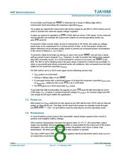
I Automatic reset to differential mode if bus failure is removed
I Full wake-up capability during failure modes
2.3 Protections
I Bus pins short-circuit safe to battery and to ground
I Thermally protected
I Bus lines protected against transients in an automotive environment
I An unpowered node does not disturb the bus lines
I Microcontroller interface without reverse current paths, if unpowered
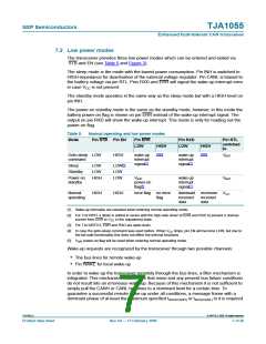
2.4 Support for low power modes
I Low current sleep mode and standby mode with wake-up via the bus lines
I Software accessible power-on reset flag
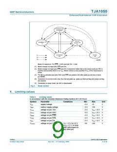
3. Quick reference data
Table 1.
Quick reference data
Symbol Parameter
Conditions
Min
4.75
−0.3
5.0
-
Typ Max Unit
VCC
supply voltage
-
-
-
-
5.25
+40
40
V
VBAT
battery supply voltage
no time limit
operating mode
load dump
V
V
58
V
IBAT
battery supply current
voltage on pin CANH
voltage on pin CANL
sleep mode at
-
25 40
µA
V
V
RTL = VWAKE = VINH
BAT = 14 V; Tamb
=
=
−40 °C to +125 °C
VCC = 0 V to 5.0 V;
BAT ≥ 0 V; no time limit;
VCANH
−58
−58
-
-
+58
V
V
V
with respect to any other
pin
VCANL
VCC = 0 V to 5.0 V;
+58
VBAT ≥ 0 V; no time limit;
with respect to any other
pin
VO(dom) dominant output voltage
on pin CANH
VTXD = 0 V; VEN = VCC
ICANH = −40 mA
ICANL = 40 mA
V
-
CC − 1.4 -
-
V
on pin CANL
-
-
1.4
1.5
V
tPD(L)
propagation delay TXD
(LOW) to RXD (LOW)
no failures;
-
µs
R
CAN_L = RCAN_H
125 Ω; CCAN_L
CAN_H = 1 nF;
see Figure 4 to Figure 6
=
=
C
[1]
Tvj
virtual junction temperature
−40
-
+150 °C
[1] Junction temperature in accordance with “IEC 60747-1”. An alternative definition is: Tvj = Tamb + P × Rth(vj-a)
where Rth(vj-a) is a fixed value to be used for the calculation of Tvj. The rating for Tvj limits the allowable
combinations of power dissipation (P) and operating ambient temperature (Tamb).
TJA1055_4
© NXP B.V. 2009. All rights reserved.
Product data sheet
Rev. 04 — 17 February 2009
2 of 26

 NXP [ NXP ]