TDF8544
NXP Semiconductors
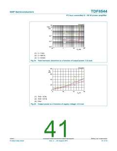
I2C-bus controlled 4 50 W power amplifier
Table 20. Characteristics …continued
Refer to test circuit (see Figure 30) at Tamb = 25 C; VP = 14.4 V; unless otherwise specified. Tested at Tamb = 25 C;
guaranteed for Tj = 40 C to +150 C; functionality is guaranteed for VP < 10 V unless otherwise specified.
Symbol
Parameter
Conditions
Min
Typ
Max
Unit
THD
total harmonic distortion
Po = 1 W to 12 W; fi = 1 kHz;
-
0.01
0.1
%
RL = 4
Po = 1 W to 12 W; fi = 10 kHz
-
-
0.2
0.4
%
%
line driver mode; Vo = 1 V RMS
and 4 V RMS
0.02
0.05
low gain mode; Po = 1 W to 12 W;
-
0.01
0.1
%
fi = 1 kHz; RL = 4
[4]
cs
channel separation
RS = 1 k; RACGND = 250
fi = 1 kHz
65
55
55
80
65
70
-
-
-
dB
dB
dB
fi = 10 kHz
[4]
[4]
SVRR
CMRR
supply voltage ripple
rejection
100 Hz to 10 kHz; RS = 1 k;
ACGND = 250 ; tested at VP =
10.5 V
R
common mode rejection
ratio
amplifier mode; Vcm = 0.3 V (p-p);
fi = 1 kHz to 3 kHz, RS = 1 k;
RACGND = 250
common mode input to
differential output (VO(dif) / VI(cm)
+ 26 dB)
55
50
65
58
-
-
dB
dB
common mode input to
common mode output
(VO(cm) / VI(cm) + 26 dB)
[5]
Vo
output voltage variation
plop during switch-on and
switch-off
from off to mute and mute to off
-
-
-
-
7.5
7.5
mV
mV
from mute to on and on to mute
(soft mute)
from off to on and on to off
(start-up diagnostic enabled)
-
-
7.5
mV
Vn(o)
output noise voltage
filter 20 Hz to 22 kHz (6th order);
RS = 1 k
mute mode
-
15
25
25
43
40
26
23
V
V
V
V
V
dB
line driver mode
-
33
line driver mode; RS = 50
amplifier mode
-
33
-
65
amplifier mode; RS = 50
single-ended in to differential out
-
60
Gv(amp)
Gv(ld)
Zi
voltage gain amplifier
mode
25.5
26.5
voltage gain line driver
mode
single-ended in to differential out
15.5
16
16.5
dB
input impedance
Tamb = 40 C to +105 C
Tamb = 0 C to 105 C
Vo / Vo(mute); Vi = 50 mV
38
55
80
62
62
92
99
99
-
k
k
dB
mute
mute attenuation
TDF8544
All information provided in this document is subject to legal disclaimers.
© NXP B.V. 2011. All rights reserved.
Product data sheet
Rev. 2 — 29 August 2011
37 of 54

 NXP [ NXP ]