Philips Semiconductors
Product specication
I2C-bus controlled 4 45 Watt power
amplier and multiple voltage regulator
TDA8589J; TDA8589xJ
compared with a reference voltage. If the output voltage of
a channel is greater than the reference voltage, bit D2 of
the associated data byte is set and read by the
microcontroller during a read instruction. Note that the
value of this bit is only meaningful when there is no input
signal and the amplifier is not muted. Offset detection is
always enabled.
AC-LOAD DETECTION
AC-load detection can be used to detect that AC-coupled
speakers are connected correctly during assembly. This
requires at least 3 periods of a 19 kHz sine wave to be
applied to the amplifier inputs. The amplifier produces a
peak output voltage which also generates a peak output
current through the AC-coupled speaker. The 19 kHz sine
wave is also audible during the test. If the amplifier detects
three current peaks that are greater than 550 mA, the
AC-load detection bit D1 of instruction byte IB1 is set to
logic 1. Three current peaks are counted to avoid false
AC-load detection which can occur if the input signal is
switched on and off. The peak current counter can be reset
by setting bit D1 of instruction byte IB1 to logic 0.
To guarantee AC-load detection, an amplifier current of
more than 550 mA is required. AC-load detection will
never occur with a current of less than 150 mA. Figure 3
shows which AC loads are detected at different output
voltages. For example, if a load is detected at an output
voltage of 2.5 V peak, the load is less than 4 . If no load
Speaker protection
If one side of a speaker is connected to ground, a missing
current protection is implemented to prevent damage to
the speaker. A fault condition is detected in a channel
when there is a mismatch between the power current in the
high side and the power current in the low side; during a
fault condition the channel will be switched off.
The load status of each channel can be read via the
I2C-bus: short to ground (one side of the speaker
connected to ground), short to VP (one side of the speaker
connected to VP), and shorted load.
is detected, the output impedance is more than 14
.
Line driver mode
An amplifier can be used as a line driver by switching it to
low gain mode. In normal mode, the gain between
single-ended input and differential output (across the load)
is 26 dB. In low gain mode the gain between single-ended
input and differential output is 20 dB.
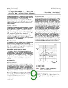
2
10
(1)
(2)
no load present
Z
o(load)
(
)
Input and AC ground capacitor values
The negative inputs to all four amplifier channels are
combined at pin ACGND. To obtain the best performance
for supply voltage ripple rejection and unwanted audible
noise, the value of the capacitor connected to pin ACGND
must be as close as possible to 4 times the value of the
input capacitor connected to the positive input of each
channel.
undefined
10
load present
Load detection
1
0
2.5
5
7.5
V
10
(V)
DC-LOAD DETECTION
o(peak)
When DC-load detection is enabled, during the start-up
cycle, a DC-offset is applied slowly to the amplifier outputs,
and the output currents are measured. If the output current
of an amplifier rises above a certain level, it is assumed
that there is a load of less than 6 and bit D5 is reset in
the associated data byte register to indicate that a load is
detected.
(1) IO(peak) = < 150 mA.
(2) IO(peak) = > 550 mA.
Fig.3 Tolerance of AC-load detection as a
function of output voltage.
Because the offset is measured during the amplifier
start-up cycle, detection is inaudible and can be performed
every time the amplifier is switched on.
LOAD DETECTION PROCEDURE
1. At start-up, enable the AC- or DC-load detection by
setting D1 of instruction byte 1 to logic 1.
2004 Feb 24
9

 NXP [ NXP ]