Philips Semiconductors
Product specication
I2C-bus controlled 4 45 Watt power
amplier and multiple voltage regulator
TDA8589J; TDA8589xJ
2. After 250 ms the DC load is detected and the mute is
released. This is inaudible and can be implemented
each time the IC is powered on.
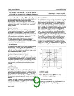
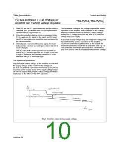
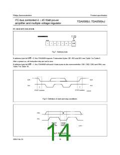
The headroom voltage is the voltage required for correct
operation of the amplifier and is defined as the voltage
difference between the level of the DC output voltage
before the VP voltage drop and the level of VP after the
voltage drop (see Fig.4).
3. When the amplifier start-up cycle is completed (after
1.5 s), apply an AC signal to the input, and DC-load
bits D5 of each data byte should be read and stored by
the microcontroller.
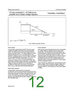
At a certain supply voltage drop, the headroom voltage will
be insufficient for correct operation of the amplifier.
To prevent unwanted audible noises at the output, the
headroom protection mode will be activated (see Fig.13).
This protection discharges the capacitors connected to
pins SVR and ACGND to increase the headroom voltage.
4. After at least 3 periods of the input signal, the load
status can be checked by reading AC-detect bits D4 of
each data byte.
The AC-load peak current counter can be reset by
setting bit D1 of instruction byte IB1 to logic 0 and then
to logic 1. Note that this will also reset the DC-load
detection bits D5 in each data byte.
Low headroom protection
The normal DC output voltage of the amplifier is set to half
the supply voltage and is related to the voltage on
pin SVR. An external capacitor is connected to pin SVR to
suppress power supply ripple. If the supply voltage drops
(at vehicle engine start), the DC output voltage will follow
slowly due to the affect of the SVR capacitor.
V
(V)
vehicle engine start
V
P
14
headroom voltage
SVR voltage
8.4
7
amplifier
DC output voltage
t (sec)
Fig.4 Amplifier output during supply voltage.
2004 Feb 24
10

 NXP [ NXP ]