NXP Semiconductors
FXTH87E
FXTH87E, Family of Tire Pressure Monitor Sensors
• Drives BKGD/PTA4 high for a brief speedup pulse to get a fast rise time (This speedup
pulse is typically one cycle of the fastest clock in the system.)
• Removes all drive to the BKGD/PTA4 pin so it reverts to high impedance
• Monitors the BKGD/PTA4 pin for the sync response pulse
The target, upon detecting the SYNC request from the host (which is a much longer low
time than would ever occur during normal BDC communications):
• Waits for BKGD/PTA4 to return to a logic high
• Delays 16 cycles to allow the host to STOP driving the high speedup pulse
• Drives BKGD/PTA4 low for 128 BDC clock cycles
• Drives a 1-cycle high speedup pulse to force a fast rise time on BKGD/PTA4
• Removes all drive to the BKGD/PTA4 pin so it reverts to high impedance
The host measures the low time of this 128-cycle sync response pulse and determines
the correct speed for subsequent BDC communications. Typically, the host can
determine the correct communication speed within a few percent of the actual target
speed and the communication protocol can easily tolerate speed errors of several
percent.
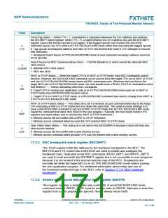
17.2.4 BDC hardware breakpoint
The BDC includes one relatively simple hardware breakpoint that compares the CPU
address bus to a 16-bit match value in the BDCBKPT register. This breakpoint can
generate a forced breakpoint or a tagged breakpoint. A forced breakpoint causes the
CPU to enter ACTIVE BACKGROUND mode at the first instruction boundary following
any access to the breakpoint address. The tagged breakpoint causes the instruction
opcode at the breakpoint address to be tagged so that the CPU will enter ACTIVE
BACKGROUND mode rather than executing that instruction if and when it reaches the
end of the instruction queue. This implies that tagged breakpoints can only be placed at
the address of an instruction opcode while forced breakpoints can be set at any address.
The breakpoint enable (BKPTEN) control bit in the BDC status and control register
(BDCSCR) is used to enable the breakpoint logic (BKPTEN = 1). When BKPTEN = 0,
its default value after reset, the breakpoint logic is disabled and no BDC breakpoints are
requested regardless of the values in other BDC breakpoint registers and control bits.
The force/tag select (FTS) control bit in BDCSCR is used to select forced (FTS = 1) or
tagged (FTS = 0) type breakpoints.
17.3 Register definition
This section contains the descriptions of the BDC registers and control bits.
This section refers to registers and control bits only by their names. A NXP-provided
equate or header file is used to translate these names into the appropriate absolute
addresses.
17.3.1 BDC registers and control bits
The BDC has two registers:
• The BDC status and control register (BDCSCR) is an 8-bit register containing control
and status bits for the BACKGROUND DEBUG controller.
• The BDC breakpoint match register (BDCBKPT) holds a 16-bit breakpoint match
address.
FXTH87ERM
All information provided in this document is subject to legal disclaimers.
© NXP B.V. 2019. All rights reserved.
Reference manual
Rev. 5.0 — 4 February 2019
169 / 183

 NXP [ NXP ]