®
Numonyx™ StrataFlash Embedded Memory (J3-65nm)
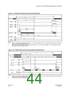
Figure 12: Single Word Asynchronous Read Waveform
R1
R2
Address [A]
CEx [E]
R3
R8
R9
OE# [G]
WE# [W]
R4
R16
R7
R6
R10
Data [D/Q]
BYTE#[F]
R12
R11
R13
R5
RP# [P]
Notes:
1.
CE low is defined as the falling edge of CE0, CE1, or CE2 that enables the device. CE high is defined as the rising edge of
X
X
CE0, CE1, or CE2 that disables the device.
2.
When reading the flash array a faster t
(R16) applies. For non-array reads, R4 applies (i.e., Status Register reads,
GLQV
query reads, or device identifier reads).
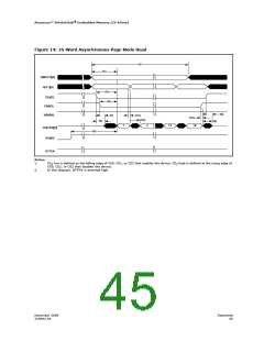
Figure 13: 4-Word Asynchronous Page Mode Read Waveform
R1
R2
A[MAX:3] [A]
A[2:1] [A]
00
01
10
11
R3
CEx [E]
R4
OE# [G]
WE# [W]
R8
R10
R9
R6
R7
R10
R15
D[15:0] [Q]
RP# [P]
1
2
3
4
R5
Note:
1.
CE low is defined as the falling edge of CE0, CE1, or CE2 that enables the device. CE high is defined as the rising edge of
X
X
CE0, CE1, or CE2 that disables the device.
2.
In this diagram, BYTE# is asserted high.
Datasheet
44
December 2008
319942-02

 NUMONYX [ NUMONYX B.V ]