properly performed, execute a RSTI command. If the chip
has reset properly, the status byte will change from hex “84”
or “C4” to hex “80” or “C0”. If this does not occur, perform an-
other reset and repeat the above steps.
Pinout Description (Continued)
Immediately after releasing the reset pin from the LM628,
the status port should read “00”. If the reset is successfully
completed, the status word will change to hex “84” or “C4”
within 1.5 ms. If the status word has not changed from hex
“00” to “84” or “C4” within 1.5 ms, perform another reset and
repeat the above steps. To be certain that the reset was
Pin 28 (16), Supply Voltage (VDD): Power supply voltage
(+5V).
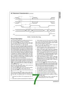
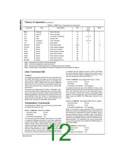
DS009219-10
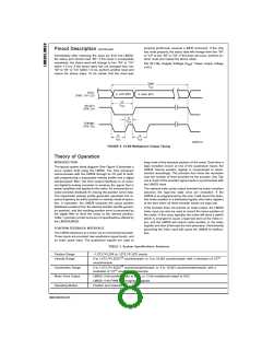
FIGURE 8. 12-Bit Multiplexed Output Timing
Theory of Operation
INTRODUCTION
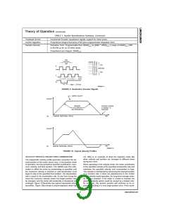
keep track of the absolute position of the motor. Each time a
logic transition occurs at one of the quadrature inputs, the
LM628 internal position register is incremented or decre-
mented accordingly. This provides four times the resolution
over the number of lines provided by the encoder. See Fig-
ure 9. Each of the encoder signal inputs is synchronized with
the LM628 clock.
The typical system block diagram (See Figure 1) illustrates a
servo system built using the LM628. The host processor
communicates with the LM628 through an I/O port to facili-
tate programming a trapezoidal velocity profile and a digital
compensation filter. The DAC output interfaces to an exter-
nal digital-to-analog converter to produce the signal that is
power amplified and applied to the motor. An incremental en-
coder provides feedback for closing the position servo loop.
The trapezoidal velocity profile generator calculates the re-
quired trajectory for either position or velocity mode of opera-
tion. In operation, the LM628 subtracts the actual position
(feedback position) from the desired position (profile genera-
tor position), and the resulting position error is processed by
the digital filter to drive the motor to the desired position.
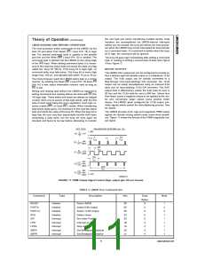
Table 1 provides a brief summary of specifications offered by
the LM628/LM629:
The optional index pulse output provided by some encoders
assumes the logic-low state once per revolution. If the
LM628 is so programmed by the user, it will record the abso-
lute motor position in a dedicated register (the index register)
at the time when all three encoder inputs are logic low.
If the encoder does not provide an index output, the LM628
index input can also be used to record the home position of
the motor. In this case, typically, the motor will close a switch
which is arranged to cause a logic-low level at the index in-
put, and the LM628 will record motor position in the index
register and alert (interrupt) the host processor. Permanently
grounding the index input will cause the LM628 to malfunc-
tion.
POSITION FEEDBACK INTERFACE
The LM628 interfaces to a motor via an incremental encoder.
Three inputs are provided: two quadrature signal inputs, and
an index pulse input. The quadrature signals are used to
TABLE 1. System Specifications Summary
Position Range
Velocity Range
−1,073,741,824 to 1,073,741,823 counts
0 to 1,073,741,823/216 counts/sample; ie, 0 to 16,383 counts/sample, with a resolution of 1/216
counts/sample
Acceleration Range
Motor Drive Output
0 to 1,073,741,823/216 counts/sample/sample; ie, 0 to 16,383 counts/sample/sample, with a
resolution of 1/216 counts/sample/sample
LM628: 8-bit parallel output to DAC, or 12-bit multiplexed output to DAC
LM629: 8-bit PWM sign/magnitude signals
Position and Velocity
Operating Modes
www.national.com
8

 NSC [ National Semiconductor ]