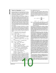
PID COMPENSATION FILTER
Theory of Operation (Continued)
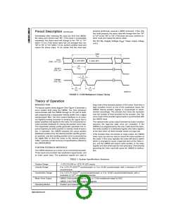
The LM628 uses a digital Proportional Integral Derivative
(PID) filter to compensate the control loop. The motor is held
at the desired position by applying a restoring force to the
motor that is proportional to the position error, plus the inte-
gral of the error, plus the derivative of the error. The following
discrete-time equation illustrates the control performed by
the LM628:
tion goes undetected, and the impeding force on the motor is
subsequently released, the motor could reach a very high
velocity in order to catch up to the desired position (which is
still advancing as specified). This condition is easily de-
tected; see commands LPEI and LPES.
All trajectory parameters are 32-bit values. Position is a
signed quantity. Acceleration and velocity are specified as
16-bit, positive-only integers having 16-bit fractions. The in-
teger portion of velocity specifies how many counts per sam-
pling interval the motor will traverse. The fractional portion
designates an additional fractional count per sampling inter-
val. Although the position resolution of the LM628 is limited
to integer counts, the fractional counts provide increased av-
erage velocity resolution. Acceleration is treated in the same
manner. Each sampling interval the commanded accelera-
tion value is added to the current desired velocity to generate
a new desired velocity (unless the command velocity has
been reached).
(1)
where u(n) is the motor control signal output at sample time
n, e(n) is the position error at sample time n, n' indi-
cates sampling at the derivative sampling rate, and
kp, ki, and kd are the discrete-time filter parameters
loaded by the users.
The first term, the proportional term, provides a restoring
force porportional to the position error, just as does a spring
obeying Hooke’s law. The second term, the integration term,
provides a restoring force that grows with time, and thus en-
sures that the static position error is zero. If there is a con-
stant torque loading, the motor will still be able to achieve
zero position error.
One determines the trajectory parameters for a desired
move as follows. If, for example, one has a 500-line shaft en-
coder, desires that the motor accelerate at one revolution per
second per second until it is moving at 600 rpm, and then de-
celerate to a stop at a position exactly 100 revolutions from
the start, one would calculate the trajectory parameters as
follows:
=
=
=
=
=
=
target position (units encoder counts)
The third term, the derivative term, provides a force propor-
tional to the rate of change of position error. It acts just like
viscous damping in a damped spring and mass system (like
a shock absorber in an automobile). The sampling interval
associated with the derivative term is user-selectable; this
capability enables the LM628 to control a wider range of in-
ertial loads (system mechanical time constants) by providing
a better approximation of the continuous derivative. In gen-
eral, longer sampling intervals are useful for low-velocity op-
erations.
let
P
R
R
P
P
*
encoder lines 4 (system resolution)
let
=
*
then
and
500
4
2000
*
2000 desired number of revolutions
=
*
2000 100 revs 200,000 counts (value to load)
=
P (coding) 00030D40 (hex code written to LM628)
=
=
clock)
=
velocity (units counts/sample)
let
let
V
T
=
sample time (seconds)
341 µs (with 6 MHz
In operation, the filter algorithm receives a 16-bit error signal
from the loop summing-junction. The error signal is saturated
at 16 bits to ensure predictable behavior. In addition to being
multiplied by filter coefficient kp, the error signal is added to
an accumulation of previous errors (to form the integral sig-
nal) and, at a rate determined by the chosen derivative sam-
pling interval, the previous error is subtracted from it (to form
the derivative signal). All filter multiplications are 16-bit op-
erations; only the bottom 16 bits of the product are used.
=
=
=
=
=
let
C
V
V
V
conversion factor 1 minute/60 seconds
*
*
*
C desired rpm
then
and
R
T
*
*
*
2000 341E−6 1/60 600 rpm
6.82 counts/sample
=
=
*
V (scaled) 6.82 65,536 446,955.52
=
V (rounded) 446,956 (value to load)
=
V (coding) 0006D1EC (hex code written to LM628)
The integral signal is maintained to 24 bits, but only the top
16 bits are used. This scaling technique results in a more us-
able (less sensitive) range of coefficient ki values. The 16
bits are right-shifted eight positions and multiplied by filter
coefficient ki to form the term which contributes to the motor
control output. The absolute magnitude of this product is
compared to coefficient il, and the lesser, appropriately
signed magnitude then contributes to the motor control sig-
nal.
=
=
=
=
=
acceleration (units counts/sample/sample)
let
A
A
A
A
*
*
*
T desired acceleration (rev/sec/sec)
R
T
*
*
*
then
and
2000 341E−6 341E-6 1 rev/sec/sec
2.33E−4 counts/sample/sample
=
=
*
A (scaled) 2.33E−4 65,536 15.24
=
A (rounded) 15 (value to load)
=
A (coding) 0000000F (hex code written to LM628)
The above position, velocity, and acceleration values must
be converted to binary codes to be loaded into the LM628.
The values shown for velocity and acceleration must be mul-
tiplied by 65,536 (as shown) to adjust for the required
integer/fraction format of the input data. Note that after scal-
ing the velocity and acceleration values, literal fractional data
cannot be loaded; the data must be rounded and converted
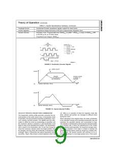
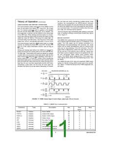
to binary. The factor of four increase in system resolution is
due to the method used to decode the quadrature encoder
signals, see Figure 9.
The derivative signal is multiplied by coefficient kd each de-
rivative sampling interval. This product contributes to the mo-
tor control output every sample interval, independent of the
user-chosen derivative sampling interval.
The kp, limited ki, and kd product terms are summed to form
a 16-bit quantity. Depending on the output mode (wordsize),
either the top 8 or top 12 bits become the motor control out-
put signal.
www.national.com
10

 NSC [ National Semiconductor ]