Data Reporting Commands (Continued)
Typical Applications
This command reads the instantaneous desired (current
temporal ) position output of the profile generator. This is the
“setpoint” input to the position-loop summing junction. The
bytes are read in most-to-least significant order.
Programming LM628 Host Handshaking (Interrupts)
A few words regarding the LM628 host handshaking will be
helpful to the system programmer. As indicated in various
portions of the above text, the LM628 handshakes with the
host computer in two ways: via the host interrupt output (Pin
17), or via polling the status byte for “interrupt” conditions.
When the hardwired interrupt is used, the status byte is also
read and parsed to determine which of six possible condi-
tions caused the interrupt.
RDRP COMMAND: ReaD Real Position
Command Code:
Bytes Read:
0A Hex
Four
Data Range:
C0000000 to 3FFFFFFF Hex
Executable During Motion: Yes
When using the hardwired interrupt it is very important that
the host interrupt service routine does not interfere with a
command sequence which might have been in progress
when the interrupt occurred. If the host interrupt service rou-
tine were to issue a command to the LM628 while it is in the
middle of an ongoing command sequence, the ongoing com-
mand will be aborted (which could be detrimental to the ap-
plication).
This command reads the current actual position of the motor.
This is the feedback input to the loop summing junction. The
bytes are read in most-to-least significant order.
RDDV COMMAND: ReaD Desired Velocity
Command Code:
Bytes Read:
07 Hex
Four
Two approaches exist for avoiding this problem. If one is us-
ing hardwired interrupts, they should be disabled at the host
prior to issuing any LM628 command sequence, and
re-enabled after each command sequence. The second ap-
proach is to avoid hardwired interrupts and poll the LM628
status byte for “interrupt” status. The status byte always re-
flects the interrupt-condition status, independent of whether
or not the interrupts have been masked.
Data Range:
C0000001 to 3FFFFFFF
Executable During Motion: Yes
This command reads the integer and fractional portions of
the instantaneous desired (current temporal ) velocity, as
used to generate the desired position profile. The bytes are
read in most-to-least significant order. The value read is
properly scaled for numerical comparison with the
user-supplied (commanded) velocity; however, because the
two least-significant bytes represent fractional velocity, only
the two most-significant bytes are appropriate for compari-
son with the data obtained via command RDRV (see below).
Also note that, although the velocity input data is constrained
to positive numbers (see command LTRJ), the data returned
by command RDDV represents a signed quantity where
negative numbers represent operation in the reverse direc-
tion.
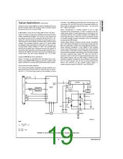
Typical Host Computer/Processor Interface
The LM628 is interfaced with the host computer/processor
via an 8-bit parallel bus. Figure 12 shows such an interface
and a minimum system configuration.
As shown in Figure 12, the LM628 interfaces with the host
data, address and control lines. The address lines are de-
coded to generate the LM628 CS input; the host address
LSB directly drives the LM628 PS input. Figure 12 also
shows an 8-bit DAC and an LM12 Power Op Amp interfaced
to the LM628.
RDRV COMMAND: ReaD Real Velocity
Command Code:
Bytes Read:
0B Hex
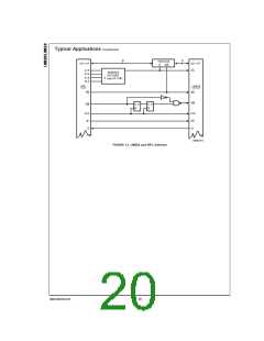
LM628 and High Performance Controller (HPC)
Interface
Two
Data Range:
C000 to 3FFF Hex, See Text
Figure 13 shows the LM628 interfaced to a National HPC
High Performance Controller. The delay and logic associated
with the WR line is used to effectively increase the write-data
hold time of the HPC (as seen at the LM628) by causing the
WR pulse to rise early. Note that the HPC CK2 output pro-
vides the clock for the LM628. The 74LS245 is used to de-
crease the read-data hold time, which is necessary when in-
terfacing to fast host busses.
Executable During Motion: Yes
This command reads the integer portion of the instanta-
neous actual velocity of the motor. The internally maintained
fractional portion of velocity is not reported because the re-
ported data is derived by reading the incremental encoder,
which produces only integer data. For comparison with the
result obtained by executing command RDDV (or the
user-supplied input value), the value returned by command
RDRV must be multiplied by 216 (shifted left 16 bit positions).
Also, as with command RDDV above, data returned by com-
mand RDRV is a signed quantity, with negative values repre-
senting reverse-direction motion.
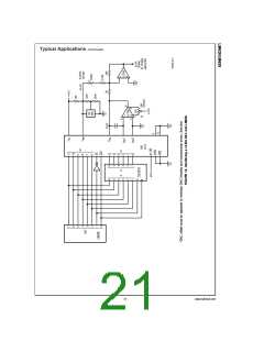
Interfacing a 12-Bit DAC
Figure 14 illustrates use of a 12-bit DAC with the LM628. The
74LS378 hex gated-D flip-flop and an inverter demultiplex
the 12-bit output. DAC offset must be adjusted to minimize
DAC linearity and monotonicity errors. Two methods exist for
making this adjustment. If the DAC1210 has been socketed,
remove it and temporarily connect a 15 kΩ resistor between
Pins 11 and 13 of the DAC socket (Pins 2 and 6 of the
LF356) and adjust the 25 kΩ potentiometer for 0V at Pin 6 of
the LF356.
RDSUM COMMAND: ReaD Integration-Term
SUMmation Value
Command Code:
Bytes Read:
0D Hex
Two
±
the Current
Data Range:
00000 Hex to
Value of the Integration Limit
If the DAC is not removable, the second method of adjust-
ment requires that the DAC1210 inputs be presented an
all-zeros code. This can be arranged by commanding the ap-
Executable During Motion: Yes
This command reads the value to which the integration term
has accumulated. The ability to read this value may be help-
ful in initially or adaptively tuning the system.
www.national.com
18

 NSC [ National Semiconductor ]