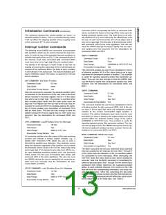
LTRJ COMMAND: Load TRaJectory Parameters
Filter Control Commands (Continued)
Command Code:
Data Bytes:
Data Ranges…
Trajectory Control
Word:
1F Hex
Executable During Motion: Yes
Two to Fourteen
The UDF command is used to update the filter parameters,
the specifics of which have been programmed via the LFIL
command. Any or all parameters (derivative-term sampling
interval, kp, ki, kd, and/or il) may be changed by the appro-
priate command(s), but command UDF must be executed to
affect the change in filter tuning. Filter updating is synchro-
nized with the calculations to eliminate erratic or spurious
behavior.
See Text
Position:
C0000000 to 3FFFFFFF Hex
00000000 to 3FFFFFFF Hex
(Pos Only)
Velocity:
Acceleration:
00000000 to 3FFFFFFF Hex
(Pos Only)
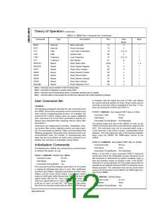
Trajectory Control Commands
The following two LM628 user commands are used for set-
ting the trajectory control parameters (position, velocity, ac-
celeration), mode of operation (position or velocity), and di-
Executable During
Motion:
Conditionally, See Text
rection (velocity mode only) as required to describe
a
desired motion or to select the mode of a manually directed
stop, and to control the timing of these system changes.
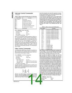
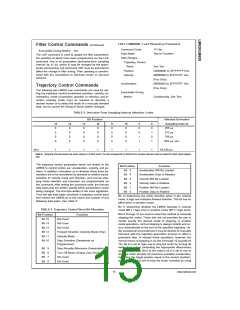
TABLE 5. Derivative-Term Sampling Interval Selection Codes
Bit Position
Selected Derivative
Sampling Interval
256 µs
15
0
14
0
13
0
12
0
11
0
10
0
9
0
0
1
1
8
0
1
0
1
0
0
0
0
0
0
512 µs
0
0
0
0
0
0
768 µs
0
0
0
0
0
0
1024 µs, etc…
thru
1
1
1
1
1
1
1
1
65,536 µs
Note 8: Sampling intervals shown are when using an 8.0 MHz clock. The 256 corresponds to 2048/8 MHz; sample intervals must be scaled for other clock frequen-
cies.
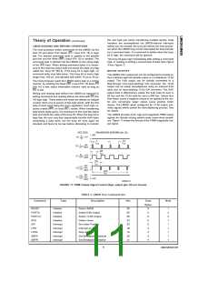
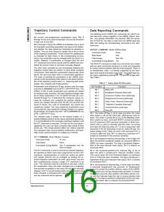
The trajectory control parameters which are written to the
Bit Position
Function
Acceleration Will Be Loaded
Acceleration Data Is Relative
Velocity Will Be Loaded
Velocity Data Is Relative
Position Will Be Loaded
Position Data Is Relative
LM628 to control motion are: acceleration, velocity, and po-
sition. In addition, indications as to whether these three pa-
rameters are to be considered as absolute or relative inputs,
selection of velocity mode and direction, and manual stop-
ping mode selection and execution are programmable via
this command. After writing the command code, the first two
data bytes that are written specify which parameter(s) is/are
being changed. The first byte written is the more significant.
Thus the two data bytes constitute a trajectory control word
that informs the LM628 as to the nature and number of any
following data bytes. See Table 6.
Bit
Bit
Bit
Bit
Bit
Bit
5
4
3
2
1
0
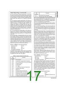
Bit 12 determines the motor direction when in the velocity
mode. A logic one indicates forward direction. This bit has no
effect when in position mode.
Bit 11 determines whether the LM628 operates in velocity
mode (Bit 11 logic one) or position mode (Bit 11 logic zero).
TABLE 6. Trajectory Control Word Bit Allocation
Bits 8 through 10 are used to select the method of manually
stopping the motor. These bits are not provided for one to
merely specify the desired mode of stopping, in position
mode operations, normal stopping is always smooth and oc-
curs automatically at the end of the specified trajectory. Un-
der exceptional circumstances it may be desired to manually
intervene with the trajectory generation process to affect a
premature stop. In velocity mode operations, however, the
normal means of stopping is via bits 8 through 10 (usually bit
10). Bit 8 is set to logic one to stop the motor by turning off
motor drive output (outputting the appropriate offset-binary
code to apply zero drive to the motor); bit 9 is set to one to
stop the motor abruptly (at maximum available acceleration,
by setting the target position equal to the current position);
and bit 10 is set to one to stop the motor smoothly by using
Bit Position
Bit 15
Function
Not Used
Not Used
Not Used
Bit 14
Bit 13
Bit 12
Forward Direction (Velocity Mode Only)
Velocity Mode
Bit 11
Bit 10
Stop Smoothly (Decelerate as
Programmed)
Bit
Bit
Bit
Bit
9
8
7
6
Stop Abruptly (Maximum Deceleration)
Turn Off Motor (Output Zero Drive)
Not Used
Not Used
15
www.national.com

 NSC [ National Semiconductor ]