Trajectory Control Commands
Data Reporting Commands
(Continued)
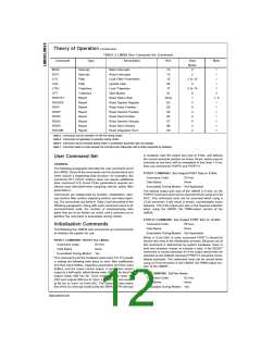
The following seven LM628 user commands are used to ob-
tain data from various registers in the LM628. Status, posi-
tion, and velocity information are reported. With the excep-
tion of RDSTAT, the data is read from the LM628 data port
after first writing the corresponding command to the com-
mand port.
the current user-programmed acceleration value. Bits
through 10 are to be used exclusively; only one bit should be
a logic one at any time.
8
Bits 0 through 5 inform the LM628 as to whether any or all of
the trajectory controlling parameters are about to be written,
and whether the data should be interpreted as absolute or
relative. The user may choose to update any or all (or none)
of the trajectory parameters. Those chosen for updating are
so indicated by logic one(s) in the corresponding bit posi-
tion(s). Any parameter may be changed while the motor is in
motion; however, if acceleration is changed then the next
STT command must not be issued until the LM628 has com-
pleted the current move or has been manually stopped.
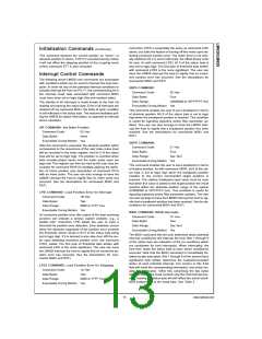
RDSTAT COMMAND: ReaD STATus Byte
Command Code:
Byte Read:
None
One
Data Range:
See Text
Executable During Motion: Yes
The RDSTAT command is really not a command, but is listed
with the other commands because it is used very frequently
to control communications with the host computer. There is
no identification code; it is directly supported by the hard-
ware and may be executed at any time. The single-byte sta-
tus read is selected by placing CS , PS and RD at logic zero.
See Table 7.
The data bytes specified by and immediately following the
trajectory control word are written in pairs which comprise
16-bit words. Each data item (parameter) requires two 16-bit
words; the word and byte order is most-to-least significant.
The order of sending the parameters to the LM628 corre-
sponds to the descending order shown in the above descrip-
tion of the trajectory control word; i.e., beginning with accel-
eration, then velocity, and finally position.
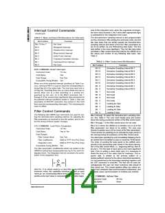
TABLE 7. Status Byte Bit Allocation
Acceleration and velocity are 32 bits, positive only, but range
only from 0 (00000000 hex) to [230]−1 (3FFFFFFF hex). The
bottom 16 bits of both acceleration and velocity are scaled
as fractional data; therefore, the least-significant integer data
bit for these parameters is bit 16 (where the bits are num-
bered 0 through 31). To determine the coding for a given ve-
locity, for example, one multiplies the desired velocity (in
counts per sample interval) times 65,536 and converts the
result to binary. The units of acceleration are counts per
sample per sample. The value loaded for acceleration must
not exceed the value loaded for velocity. Position is a signed,
32-bit integer, but ranges only from −[230] (C0000000 hex) to
[230]−1 (3FFFFFFF Hex).
Bit Position
Bit 7
Function
Motor Off
Bit 6
Breakpoint Reached [Interrupt]
Excessive Position Error [Interrupt]
Wraparound Occurred [Interrupt]
Index Pulse Observed [Interrupt]
Trajectory Complete [Interrupt]
Command Error [Interrupt]
Busy Bit
Bit 5
Bit 4
Bit 3
Bit 2
Bit 1
Bit 0
Bit 7, the motor-off flag, is set to logic one when the motor
drive output is off (at the half-scale, offset-binary code for
zero). The motor is turned off by any of the following condi-
tions: power-up reset, command RESET, excessive position
error (if command LPES had been executed), or when com-
mand LTRJ is used to manually stop the motor via turning
the motor off. Note that when bit 7 is set in conjunction with
command LTRJ for producing a manual, motor-off stop, the
actual setting of bit 7 does not occur until command STT is
issued to affect the stop. Bit 7 is cleared by command STT,
except as described in the previous sentence.
The required data is written to the primary buffers of a
double-buffered scheme by the above described operations;
it is not transferred to the secondary (working) registers until
the STT command is executed. This fact can be used advan-
tageously; the user can input numerous data ahead of their
actual use. This simple pipeline effect can relieve potential
host computer data communications bottlenecks, and facili-
tates easier synchronization of multiple-axis controls.
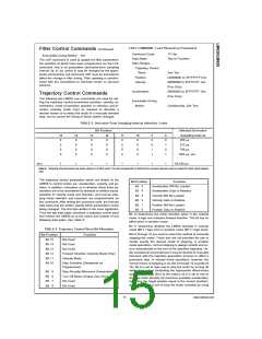
STT COMMAND: STarT Motion Control
Bit 6, the breakpoint-reached interrupt flag, is set to logic one
when the position breakpoint loaded via command SBPA or
SBPR has been exceeded. The flag is functional indepen-
dent of the host interrupt mask status. Bit 6 is cleared via
command RSTI.
Command Code:
Data Bytes:
01 Hex
None
Executable During Motion: Yes, if acceleration has not
been changed
The STT command is used to execute the desired trajectory,
the specifics of which have been programmed via the LTRJ
command. Synchronization of multi-axis control (to within
one sample interval) can be arranged by loading the re-
quired trajectory parameters for each (and every) axis and
then simultaneously issuing a single STT command to all
axes. This command may be executed at any time, unless
the acceleration value has been changed and a trajectory
has not been completed or the motor has not been manually
stopped. If STT is issued during motion and acceleration has
been changed, a command error interrupt will be generated
and the command will be ignored.
Bit 5, the excessive-position-error interrupt flag, is set to
logic one when a position-error interrupt condition exists.
This occurs when the error threshold loaded via command
LPEI or LPES has been exceeded. The flag is functional in-
dependent of the host interrupt mask status. Bit 5 is cleared
via command RSTI.
Bit 4, the wraparound interrupt flag, is set to logic one when
a numerical “wraparound” has occurred. To “wraparound”
means to exceed the position address space of the LM628,
which could occur during velocity mode operation. If a wrap-
around has occurred, then position information will be in er-
ror and this interrupt helps the user to ensure position data
integrity. The flag is functional independent of the host inter-
rupt mask status. Bit 4 is cleared via command RSTI.
www.national.com
16

 NSC [ National Semiconductor ]