tude of the integration term; when the magnitude of integra-
tion term value exceeds il, the il value (with appropriate sign)
is substituted for the integration term value.
Interrupt Control Commands
(Continued)
The derivative-term sampling interval is also programmable
via this command. After writing the command code, the first
two data bytes that are written specify the derivative-term
sampling interval and which of the four filter parameters is/
are to be written via any forthcoming data bytes. The first
byte written is the more significant. Thus the two data bytes
constitute a filter control word that informs the LM628 as to
the nature and number of any following data bytes. See
Table 4.
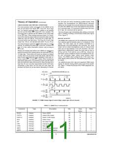
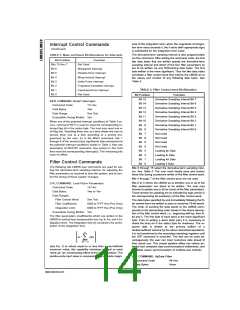
TABLE 3. Mask and Reset Bit Allocations for Interrupts
Bit Position
Bits 15 thru 7
Bit 6
Function
Not Used
Breakpoint Interrupt
Position-Error Interrupt
Wrap-Around Interrupt
Index-Pulse Interrupt
Trajectory-Complete Interrupt
Command-Error Interrupt
Not Used
Bit 5
Bit 4
Bit 3
Bit 2
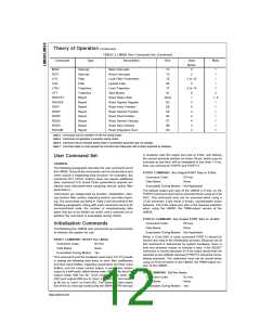
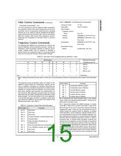
TABLE 4. Filter Control word Bit Allocation
Bit 1
Bit 0
Bit Position
Bit 15
Function
Derivative Sampling Interval Bit 7
Derivative Sampling Interval Bit 6
Derivative Sampling Interval Bit 5
Derivative Sampling Interval Bit 4
Derivative Sampling Interval Bit 3
Derivative Sampling Interval Bit 2
Derivative Sampling Interval Bit 1
Derivative Sampling Interval Bit 0
Not Used
RSTI COMMAND: ReSeT Interrupts
Bit 14
Command Code:
Data Bytes:
1D Hex
Two
Bit 13
Bit 12
Data Range:
See Text
Bit 11
Executable During Motion: Yes
Bit 10
When one of the potential interrupt conditions of Table 3 oc-
curs, command RSTI is used to reset the corresponding in-
terrupt flag bit in the status byte. The host may reset one or
all flag bits. Resetting them one at a time allows the host to
service them one at a time according to a priority pro-
grammed by the user. As in the MSKI command, bits 1
through 6 of the second (less significant) byte correspond to
the potential interrupt conditions shown in Table 3. Also see
description of RDSTAT command. Any zero(s) in this 6-bit
field reset the corresponding interrupt(s). The remaining bits
have no effect.
Bit
Bit
Bit
Bit
Bit
Bit
Bit
Bit
Bit
Bit
9
8
7
6
5
4
3
2
1
0
Not Used
Not Used
Not Used
Loading kp Data
Loading ki Data
Loading kd Data
Filter Control Commands
Loading il Data
The following two LM628 user commands are used for set-
ting the derivative-term sampling interval, for adjusting the
filter parameters as required to tune the system, and to con-
trol the timing of these system changes.
Bits 8 through 15 select the derivative-term sampling inter-
val. See Table 5. The user must locally save and restore
these bits during successive writes of the filter control word.
Bits 4 through 7 of the filter control word are not used.
Bits 0 to 3 inform the LM628 as to whether any or all of the
filter parameters are about to be written. The user may
choose to update any or all (or none) of the filter parameters.
Those chosen for updating are so indicated by logic one(s) in
the corresponding bit position(s) of the filter control word.
LFIL COMMAND: Load FILter Parameters
Command Code:
Data Bytes:
1E Hex
Two to Ten
Data Ranges…
Filter Control Word:
Filter Coefficients:
Integration Limit:
See Text
The data bytes specified by and immediately following the fil-
ter control word are written in pairs to comprise 16-bit words.
The order of sending the data words to the LM628 corre-
sponds to the descending order shown in the above descrip-
tion of the filter control word; i.e., beginning with kp, then ki,
kd and il. The first byte of each word is the more-significant
byte. Prior to writing a word (byte pair) it is necessary to
check the busy bit in the status byte for readiness. The re-
0000 to 7FFF Hex (Pos Only)
0000 to 7FFF Hex (Pos Only)
Executable During Motion: Yes
The filter parameters (coefficients) which are written to the
LM628 to control loop compensation are: kp, ki, kd, and il (in-
tegration limit). The integration limit (il) constrains the contri-
bution of the integration term
quired data is written to the primary buffers of
a
double-buffered scheme by the above described operations;
it is not transferred to the secondary (working) registers until
the UDF command is executed. This fact can be used ad-
vantageously; the user can input numerous data ahead of
their actual use. This simple pipeline effect can relieve po-
tential host computer data communications bottlenecks, and
facilitates easier synchronization of multiple-axis controls.
(see Eq. 1) to values equal to or less than a user-defined
maximum value; this capability minimizes integral or reset
“wind-up” (an overshooting effect of the integral action). The
positive-only input value is compared to the absolute magni-
UDF COMMAND: UpDate Filter
Command Code:
Data Bytes:
04 Hex
None
www.national.com
14

 NSC [ National Semiconductor ]