encoders. The LM628 will work with both encoder types, but
commands SIP and RDIP will not be meaningful without an
index pulse (or alternative input for this input … be sure to tie
Pin 1 high if not used).
Typical Applications (Continued)
propriate move via the LM628, but with no feedback from the
system encoder. When the all-zeros code is present, adjust
the pot for 0V at Pin 6 of the LF356.
Some consideration is merited relative to use in high
Gaussian-noise environments. If noise is added to the en-
coder inputs (either or both inputs) and is such that it is not
sustained until the next encoder transition, the LM628 de-
coder logic will reject it. Noise that mimics quadrature counts
or persists through encoder transitions must be eliminated
by appropriate EMI design.
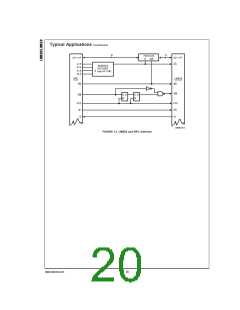
A Monolithic Linear Drive Using LM12 Power Op Amp
Figure 15 shows a motor-drive amplifier built using the LM12
Power Operational Amplifier. This circuit is very simple and
can deliver up to 8A at 30V (using the LM12L/LM12CL). Re-
sistors R1 and R2 should be chosen to set the gain to pro-
vide maximum output voltage consistent with maximum input
voltage. This example provides a gain of 2.2, which allows
Simple digital “filtering” schemes merely reduce susceptibil-
ity to noise (there will always be noise pulses longer than the
filter can eliminate). Further, any noise filtering scheme re-
duces decoder bandwidth. In the LM628 it was decided
(since simple filtering does not eliminate the noise problem)
to not include a noise filter in favor of offering maximum pos-
sible decoder bandwidth. Attempting to drive encoder signals
too long a distance with simple TTL lines can also be a
source of “noise” in the form of signal degradation (poor rise-
time and/or ringing). This can also cause a system to lose
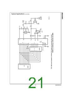
positional integrity. Probably the most effective countermea-
sure to noise induction can be had by using balanced-line
drivers and receivers on the encoder inputs. Figure 17
shows circuitry using the DS26LS31 and DS26LS32.
±
±
for amplifier output saturation at 22V with a 10V input, as-
±
suming power supply voltages of 30V. The amplifier gain
should not be higher than necessary because the system is
non-linear when saturated, and because gain should be con-
trolled by the LM628. The LM12 can also be configured as a
current driver, see 1987 Linear Databook, Vol. 1, p. 2–280.
Typical PWM Motor Drive Interfaces
Figure 16 shows an LM18298 dual full-bridge driver inter-
faced to the LM629 PWM outputs to provide a switch-mode
power amplifier for driving small brush/commutator motors.
Incremental Encoder Interface
The incremental (position feedback) encoder interface con-
sists of three lines: Phase A (Pin 2), Phase B (Pin 3), and In-
dex (Pin 1). The index pulse output is not available on some
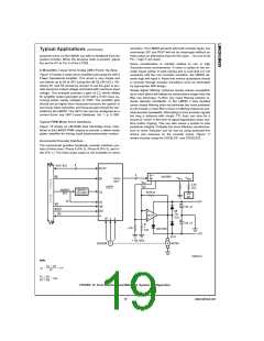
DS009219-14
Note:
FIGURE 12. Host Interface and Minimum System Configuration
19
www.national.com

 NSC [ National Semiconductor ]