Application Hints (Continued)
DS007971-11
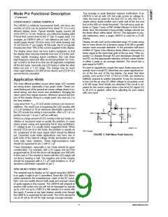
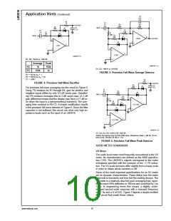
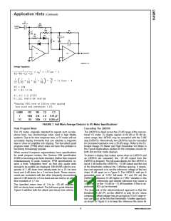
D1, D2: 1N914 or 1N4148
Average Peak
DS007971-12
R2
R3
1k
100k
1k
D1, D2: 1N914 or 1N4148
100k
FIGURE 5. Precision Full-Wave Average Detector
=
=
1
R1 R2 for A
V
=
=
10
R1 R2/10 for A
V
=
C1 10/R1
FIGURE 4. Precision Half-Wave Rectifier
For precision full-wave averaging use the circuit in Figure 5.
%
Using 1 resistors for R1 through R4, gain for positive and
negative signal differs by only 0.5 dB worst case. Substitut-
%
ing 5 resistors increases this to 2 dB worst case. (A 2 dB
±
gain difference means that the display may have a 1 dB er-
ror when the input is a nonsymmetrical transient). The aver-
aging time constant is R5•C2. A simple modification results
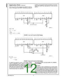
in the precision full-wave detector of Figure 6. Since the filter
capacitor is not buffered, this circuit can drive only high im-
pedance loads such as the input of an LM3916.
DS007971-13
D1, D2, D3, D4: 1N914 OR 1N4148
Attack and decay time to DIN PPM spec. Response down 1 dB for 10 ms
tone burst. Decays 20 dB in 1.5s.
FIGURE 6. Precision Full-Wave Peak Detector
AUDIO METER STANDARDS
VU Meter
The audio level meter most frequently encountered is the VU
meter. Its characteristics are defined as the ANSI specifica-
tion C165. The LM3916’s outputs correspond to the meter
indications specified with the omission of the −2 VU indica-
tion. The VU scale divisions differ slightly from a linear scale
in order to obtain whole numbers in dB.
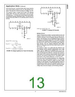
Some of the most important specifications for an AC meter
are its dynamic characteristics. These define how the meter
responds to transients and how fast the reading decays. The
VU meter is a relatively slow full-wave averaging type, speci-
%
fied to reach 99 deflection in 300 ms and overshoot by 1 to
%
1.5 . In engineering terms this means a slightly under-
damped second order response with a resonant frequency
of 2.1 Hz and a Q of 0.62. Figure 7 depicts a simple rectifier/
filter circuit that meets these criteria.
www.national.com
10

 NSC [ National Semiconductor ]