#
as the input voltage reaches the threshold of LED 11, pin 9
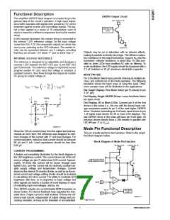
Mode Pin Functional Description
#
of driver 1 is pulled an LED drop (1.5V or more) below
LED. This condition is sensed by comparator C2, refer-
enced 600 mV below VLED. This forces the output of C2 low,
which shuts off output transistor Q2, extinguishing LED 10.
LED is sensed via the 20k resistor connected to pin 11. The
very small current (less than 100 µA) that is diverted from
(Continued)
V
DOT OR BAR MODE SELECTION
#
The voltage at pin 9 is sensed by comparator C1, nominally
referenced to (V+ −100 mV). The chip is in bar mode when
pin 9 is above this level; otherwise it’s in dot mode. The com-
parator is designed so that pin 9 can be left open circuit for
dot mode.
V
#
LED 9 does not noticeably affect its intensity.
An auxiliary current source at pin 1 keeps at least 100 µA
#
flowing through LED 11 even if the input voltage rises high
Taking into account comparator gain and variation in the
100 mV reference level, pin 9 should be no more than 20 mV
below V+ for bar mode and more than 200 mV below V+ (or
open circuit) for dot mode. In most applications, pin 9 is ei-
ther open (dot mode) or tied to V+ (bar mode). In bar mode,
pin 9 should be connected directly to pin 3. Large currents
drawn from the power supply (LED current, for example)
should not share this path so that large IR drops are avoided.
enough to extinguish the LED. This ensures that pin 9 of
#
#
driver 1 is held low enough to force LED 10 off when any
higher LED is illuminated. While 100 µA does not normally
produce significant LED illumination, it may be noticeable
when using high-efficiency LEDs in a dark environment. If
this is bothersome, the simple cure is to shunt LED 11 (and
LED 1) with a 10k resistor. The 1V 1R drop is more than the
#
#
#
900 mV worst case required to hold off LED 10 yet small
#
enough that LED 11 does not conduct significantly.
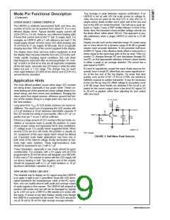
DOT MODE CARRY
In some circuits a number of outputs on the higher device
are not used. Examples include the high resolution VU meter
and the expanded range VU meter circuits (see Typical Ap-
plications). To provide the proper carry sense voltage in dot
mode, the LEDs of the higher driver IC are tied to VLED
through two series-connected diodes as shown in Figure 2.
Shunting the diodes with a 1k resistor provides a path for
driver leakage current.
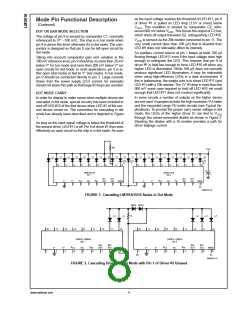
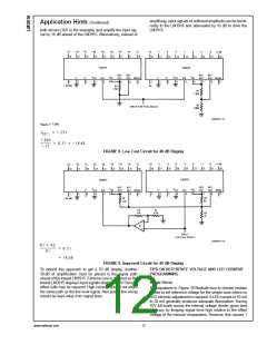
In order for display to make sense when multiple drivers are
cascaded in dot mode, special circuitry has been included to
shut off LED #10 of the first device when LED #1 of the sec-
ond device comes on. The connection for cascading in dot
mode has already been described and is depicted in Figure
1.
As long as the input signal voltage is below the threshold of
#
#
the second driver, LED 11 is off. Pin 9 of driver 1 thus sees
effectively an open circuit so the chip is in dot mode. As soon
DS007971-8
FIGURE 1. Cascading LM3914/15/16 Series in Dot Mode
DS007971-9
#
FIGURE 2. Cascading Drivers in Dot Mode with Pin 1 of Driver 2 Unused
www.national.com
8

 NSC [ National Semiconductor ]