Application Hints (Continued)
mA to flow from pin 7 into the divider which means that the
LED current will be at least 10 mA. R1 will typically be be-
tween 1 kΩ and 5 kΩ. To trim the reference voltage, vary R2.
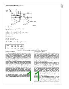
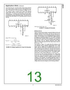
The current in Figure 11 shows how to add a LED intensity
control which can vary LED current from 5 mA to 28 mA.
=
Choosing VREF 5V lowers the current drawn by the ladder,
increasing the intensity adjustment range. The reference ad-
justment has some effect on LED intensity but the reverse is
not true.
DS007971-18
=
5V
@
5 mA ≤ I
≤ 28 mA
V
LED
REF
FIGURE 11. Varying LED Intensity
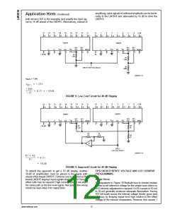
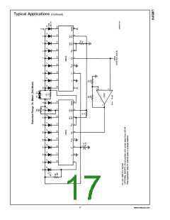
Multiple Drivers
Figure 12 shows how to obtain a common reference trim and
intensity control for two drivers. The two ICs may be con-
nected in cascade or may be handling separate channels for
stereo. This technique can be extended for larger numbers
of drivers by varying the values of R1, R2 and R3. Because
the LM3915 has a greater ladder resistance, R5 was picked
less than R7 in such a way as to provide equal reference
load currents. The ICs’ internal references track within
100 mV so that worst case error from chip to chip is only 0.2
DS007971-17
=
dB for VREF 5V.
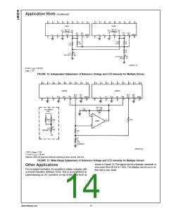
The scheme in Figure 13 is useful when the reference and
LED intensity must be adjusted independently over a wide
range. The RHI voltage can be adjusted from 1.2V to 10V
with no effect on LED current. Since the internal divider here
does not load down the reference, minimum LED current is
much lower. At the minimum recommended reference load
of 80 µA, LED current is about 0.8 mA. The resistor values
shown give a LED current range from 1.5 mA to 25 mA.
FIGURE 10. Design Equations for Fixed LED Intensity
At the low end of the intensity adjustment, the voltage drop
across the 510Ω current-sharing resistors is so small that
chip to chip variation in reference voltage may yield a visible
variation in LED intensity. The optional approach shown of
connecting the bottom end of the intensity control pot to a
negative supply overcomes this problem by allowing a larger
voltage drop across the (larger) current-sharing resistors.
13
www.national.com

 NSC [ National Semiconductor ]