Application Hints (Continued)
DS007971-19
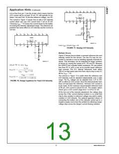
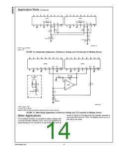
5 mA ≤ I
≤ 28 mA
LED
5V
=
V
REF
FIGURE 12. Independent Adjustment of Reference Voltage and LED Intensity for Multiple Drivers
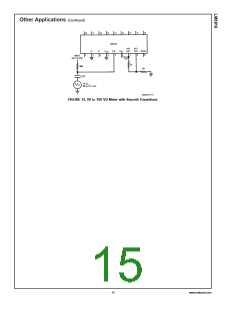
DS007971-20
1.25V ≤ V
≤ 10V
REF
1.5 mA ≤ I
≤ 25 mA
LED
Optional circuit for improved intensity matching at low currents. See text.
FIGURE 13. Wide-Range Adjustment of Reference Voltage and LED intensity for Multiple Drivers
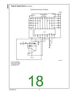
shown in Figure 14. The signal can be a triangle, sawtooth or
sine wave from 60 Hz to 1 kHz. The display can be run in ei-
ther dot or bar mode.
Other Applications
For increased resolution, it’s possible to obtain a display with
a smooth transition between LEDs. This is accomplished by
superimposing an AC waveform on top of the input level as
www.national.com
14

 NSC [ National Semiconductor ]