Application Hints
DS012316-26
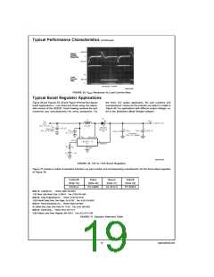
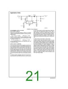
FIGURE 41. Boost Regulator
the main output. When the output voltage drops to 80
% of its
PROGRAMMING OUTPUT VOLTAGE
(SELECTING R1 AND R2)
nominal value, the frequency will drop to 25 kHz. With a
lower frequency, off times are larger. With the longer off
times, the transformer can release all of its stored energy be-
fore the switch turns back on. Hence, the switch turns on ini-
tially with zero current at its collector. In this condition, the
switch current limit will limit the peak current, saving the de-
vice.
Referring to the adjustable regulator in Figure 41, the output
voltage is programmed by the resistors R1 and R2 by the fol-
lowing formula:
=
=
where VREF 1.23V
VOUT VREF (1 + R1/R2)
Resistors R1 and R2 divide the output voltage down so that
it can be compared with the 1.23V internal reference. With
R2 between 1k and 5k, R1 is:
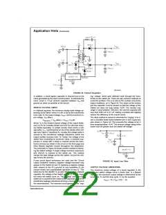
FLYBACK REGULATOR INPUT CAPACITORS
=
=
where VREF 1.23V
R1 R2 (VOUT/VREF − 1)
A flyback regulator draws discontinuous pulses of current
from the input supply. Therefore, there are two input capaci-
tors needed in a flyback regulator; one for energy storage
and one for filtering (see Figure 42). Both are required due to
the inherent operation of a flyback regulator. To keep a
stable or constant voltage supply to the LM2587, a storage
capacitor (≥100 µF) is required. If the input source is a reciti-
fied DC supply and/or the application has a wide tempera-
ture range, the required rms current rating of the capacitor
might be very large. This means a larger value of capaci-
tance or a higher voltage rating will be needed of the input
capacitor. The storage capacitor will also attenuate noise
which may interfere with other circuits connected to the
same input supply voltage.
For best temperature coefficient and stability with time, use
1% metal film resistors.
SHORT CIRCUIT CONDITION
Due to the inherent nature of boost regulators, when the out-
put is shorted (see Figure 41), current flows directly from the
input, through the inductor and the diode, to the output, by-
passing the switch. The current limit of the switch does not
limit the output current for the entire circuit. To protect the
load and prevent damage to the switch, the current must be
externally limited, either by the input supply or at the output
with an external current limit circuit. The external limit should
be set to the maximum switch current of the device, which is
5A.
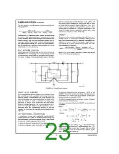
In a flyback regulator application (Figure 42), using the stan-
dard transformers, the LM2587 will survive a short circuit to
21
www.national.com

 NSC [ National Semiconductor ]