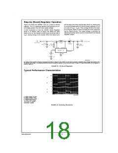
Step-Up (Boost) Regulator Operation
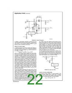
Figure 33 shows the LM2587 used as a step-up (boost)
regulator. This is a switching regulator that produces an out-
put voltage greater than the input supply voltage.
off, the lower end of the inductor flies above VIN, discharging
its current through diode (D) into the output capacitor (COUT
)
at a rate of (VOUT − VIN)/L. Thus, energy stored in the induc-
tor during the switch on time is transferred to the output dur-
ing the switch off time. The output voltage is controlled by
adjusting the peak switch current, as described in the flyback
regulator section.
A brief explanation of how the LM2587 Boost Regulator
works is as follows (refer to Figure 33). When the NPN
switch turns on, the inductor current ramps up at the rate of
V
IN/L, storing energy in the inductor. When the switch turns
DS012316-19
By adding a small number of external components (as shown in Figure 33), the LM2587 can be used to produce a regulated output voltage that is greater than
the applied input voltage. The switching waveforms observed during the operation of this circuit are shown in Figure 34. Typical performance of this regulator is
shown in Figure 35.
FIGURE 33. 12V Boost Regulator
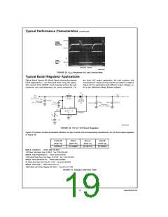
Typical Performance Characteristics
DS012316-20
A: Switch Voltage, 10 V/div
B: Switch Current, 5 A/div
C: Inductor Current, 5 A/div
D: Output Ripple Voltage,
100 mV/div, AC-Coupled
Horizontal: 2 µs/div
FIGURE 34. Switching Waveforms
www.national.com
18

 NSC [ National Semiconductor ]