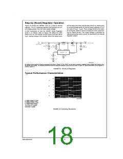
Typical Performance Characteristics (Continued)
DS012316-21
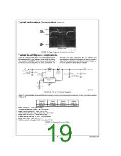
FIGURE 35. VOUT Response to Load Current Step
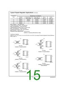
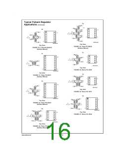
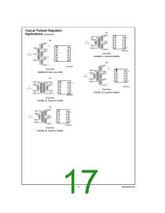
Typical Boost Regulator Applications
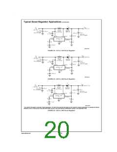
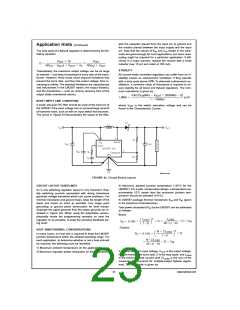
Figure 36 and Figures 38, 39 and Figure 40 show four typical
boost applications) — one fixed and three using the adjust-
able version of the LM2587. Each drawing contains the part
number(s) and manufacturer(s) for every component. For
the fixed 12V output application, the part numbers and
manufacturers’ names for the inductor are listed in a table in
Figure 40. For applications with different output voltages, re-
fer to the Switchers Made Simple software.
DS012316-22
FIGURE 36. +5V to +12V Boost Regulator
Figure 37 contains a table of standard inductors, by part number and corresponding manufacturer, for the fixed output regulator
of Figure 36.
Coilcraft
(Note 19)
R4793-A
Pulse
Renco
Schott
(Note 22)
67146520
(Note 20)
PE-53900
(Note 21)
RL-5472-5
Note 19: Coilcraft Inc.,: Phone: (800) 322-2645
1102 Silver Lake Road, Cary, IL 60013: Fax: (708) 639-1469
Note 20: Pulse Engineering Inc.,: Phone: (619) 674-8100
12220 World Trade Drive, San Diego, CA 92128: Fax: (619) 674-8262
Note 21: Renco Electronics Inc.,: Phone: (800) 645-5828
60 Jeffryn Blvd. East, Deer Park, NY 11729: Fax: (516) 586-5562
Note 22: Schott Corp.,: Phone: (612) 475-1173
1000 Parkers Lane Road, Wayzata, MN 55391: Fax: (612) 475-1786
FIGURE 37. Inductor Selection Table
19
www.national.com

 NSC [ National Semiconductor ]