Typical Flyback Regulator Applications (Continued)
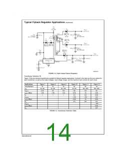
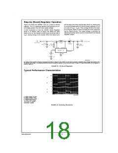
DS012316-18
FIGURE 12. Triple-Output Flyback Regulator
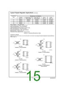
Transformer Selection (T)
Figure 13 lists the standard transformers available for flyback regulator applications. Included in the table are the turns ratio(s) for
each transformer, as well as the output voltages, input voltage ranges, and the maximum load currents for each circuit.
Applications
Transformers
VIN
Figure 7
T1
Figure 8
T1
Figure 9
T1
Figure 10
T2
Figure 11
T3
Figure 12
T4
4V–6V
3.3V
1.8A
1
4V–6V
5V
8V–16V
12V
4V–6V
12V
18V–36V
12V
18V–36V
5V
VOUT1
IOUT1 (Max)
N1
1.4A
1
1.2A
1
0.3A
2.5
1A
2.5A
0.35
0.8
VOUT2
−12V
0.3A
2.5
−12V
1A
12V
IOUT2 (Max)
N2
0.5A
0.8
0.8
VOUT3
−12V
0.5A
0.8
IOUT3 (Max)
N3
FIGURE 13. Transformer Selection Table
www.national.com
14

 NSC [ National Semiconductor ]