8.4.2 SYNCHRONOUS MODE
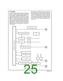
8.0 USART (Continued)
In this mode data is transferred synchronously with the
clock. Data is transmitted on the rising edge and received on
the falling edge of the synchronous clock.
ETI: This bit enables/disables interrupt from the transmitter
section. Read/Write, cleared on reset.
ETI = 0
ETI = 1
Interrupt from the transmitter is disabled.
Interrupt from the transmitter is enabled.
This mode is selected by setting SSEL bit in the ENUI regis-
ter. The input frequency to the USART is the same as the
baud rate.
8.3 Associated I/O Pins
When an external clock input is selected at the CKX pin, data
transmit and receive are performed synchronously with this
clock through TDX/RDX pins.
Data is transmitted on the TDX pin and received on the RDX
pin. TDX is the alternate function assigned to Port L pin L2;
it is selected by setting ETDX (in the ENUI register) to one.
RDX is an inherent function of Port L pin L3, requiring no
setup.
If data transmit and receive are selected with the CKX pin as
clock output, the device generates the synchronous clock
output at the CKX pin. The internal baud rate generator is
used to produce the synchronous clock. Data transmit and
receive are performed synchronously with this clock.
The baud rate clock for the USART can be generated on-
chip, or can be taken from an external source. Port L pin L1
(CKX) is the external clock I/O pin. The CKX pin can be ei-
ther an input or an output, as determined by Port L Configu-
ration and Data registers (Bit 1). As an input, it accepts a
clock signal which may be selected to drive the transmitter
and/or receiver. As an output, it presents the internal Baud
Rate Generator output.
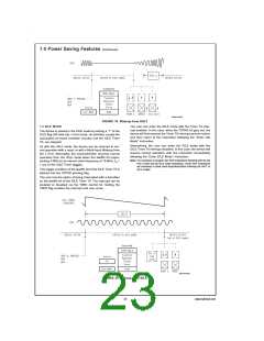
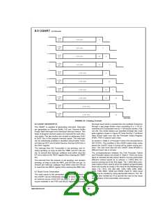
8.5 FRAMING FORMATS
The USART supports several serial framing formats (Figure
23). The format is selected using control bits in the ENU,
ENUR and ENUI registers.
The first format (1, 1a, 1b, 1c) for data transmission (CHL0 =
1, CHL1 = 0) consists of Start bit, seven Data bits (excluding
parity) and 7/8, one or two Stop bits. In applications using
parity, the parity bit is generated and verified by hardware.
8.4 USART Operation
The USART has two modes of operation: asynchronous
mode and synchronous mode.
The second format (CHL0 = 0, CHL1 = 0) consists of one
Start bit, eight Data bits (excluding parity) and 7/8, one or
two Stop bits. Parity bit is generated and verified by hard-
ware.
8.4.1 ASYNCHRONOUS MODE
This mode is selected by resetting the SSEL (in the ENUI
register) bit to zero. The input frequency to the USART is 16
times the baud rate.
The third format for transmission (CHL0 = 0, CHL1 = 1) con-
sists of one Start bit, nine Data bits and 7/8, one or two Stop
bits. This format also supports the USART “ATTENTION”
feature. When operating in this format, all eight bits of TBUF
and RBUF are used for data. The ninth data bit is transmitted
and received using two bits in the ENU and ENUR registers,
called XBIT9 and RBIT9. RBIT9 is a read only bit. Parity is
not generated or verified in this mode.
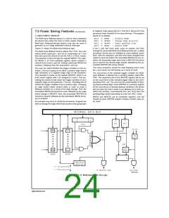
The TSFT and TBUF registers double-buffer data for trans-
mission. While TSFT is shifting out the current character on
the TDX pin, the TBUF register may be loaded by software
with the next byte to be transmitted. When TSFT finishes
transmitting the current character the contents of TBUF are
transferred to the TSFT register and the Transmit Buffer
Empty Flag (TBMT in the ENU register) is set. The TBMT
flag is automatically reset by the USART when software
loads a new character into the TBUF register. There is also
the XMTG bit which is set to indicate that the USART is
transmitting. This bit gets reset at the end of the last frame
(end of last Stop bit). TBUF is a read/write register.
For any of the above framing formats, the last Stop bit can
be programmed to be 7/8th of a bit in length. If two Stop bits
are selected and the 7/8th bit is set (selected), the second
Stop bit will be 7/8th of a bit in length.
The parity is enabled/disabled by PEN bit located in the ENU
register. Parity is selected for 7- and 8-bit modes only. If par-
ity is enabled (PEN = 1), the parity selection is then per-
formed by PSEL0 and PSEL1 bits located in the ENU regis-
ter.
The RSFT and RBUF registers double-buffer data being re-
ceived. The USART receiver continually monitors the signal
on the RDX pin for a low level to detect the beginning of a
Start bit. Upon sensing this low level, it waits for half a bit
time and samples again. If the RDX pin is still low, the re-
ceiver considers this to be a valid Start bit, and the remaining
bits in the character frame are each sampled a single time, at
the mid-bit position. Serial data input on the RDX pin is
shifted into the RSFT register. Upon receiving the complete
character, the contents of the RSFT register are copied into
the RBUF register and the Received Buffer Full Flag (RBFL)
is set. RBFL is automatically reset when software reads the
character from the RBUF register. RBUF is a read only reg-
ister. There is also the RCVG bit which is set high when a
framing error occurs and goes low once RDX goes high.
TBMT, XMTG, RBFL and RCVG are read only bits.
Note that the XBIT9/PSEL0 bit located in the ENU register
serves two mutually exclusive functions. This bit programs
the ninth bit for transmission when the USART is operating
with nine data bits per frame. There is no parity selection in
this framing format. For other framing formats XBIT9 is not
needed and the bit is PSEL0 used in conjunction with PSEL1
to select parity.
The frame formats for the receiver differ from the transmitter
in the number of Stop bits required. The receiver only re-
quires one Stop bit in a frame, regardless of the setting of the
Stop bit selection bits in the control register. Note that an im-
plicit assumption is made for full duplex USART operation
that the framing formats are the same for the transmitter and
receiver.
27
www.national.com

 NSC [ National Semiconductor ]