DOE = 1
Indicates the occurrence of a Data Overrun Er-
ror.
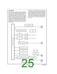
8.0 USART (Continued)
8.1 USART CONTROL AND STATUS REGISTERS
FE: Flags a Framing Error. Read only, cleared on read,
The operation of the USART is programmed through three
registers: ENU, ENUR and ENUI.
cleared on reset.
FE = 0
Indicates no Framing Error has been detected
since the last time the ENUR register was read.
8.2 DESCRIPTION OF USART REGISTER BITS
FE = 1
Indicates the occurrence of a Framing Error.
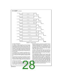
ENU-USART Control and Status Register (Address at 0BA)
PE: Flags a Parity Error. Read only, cleared on read, cleared
on reset.
PEN PSEL1 XBIT9/ CHL1
CHL0
ERR
RBFL TBMT
PSEL0
PE = 0
Indicates no Parity Error has been detected since
the last time the ENUR register was read.
Bit 7
Bit 0
PE = 1
Indicates the occurrence of a Parity Error.
PEN: This bit enables/disables Parity (7- and 8-bit modes
only). Read/Write, cleared on reset.
SPARE: Reserved for future use. Read/Write, cleared on re-
set.
PEN = 0
PEN = 1
Parity disabled.
Parity enabled.
RBIT9: Contains the ninth data bit received when the US-
ART is operating with nine data bits per frame. Read only,
cleared on reset.
PSEL1, PSEL0: Parity select bits. Read/Write, cleared on
reset.
ATTN: ATTENTION Mode is enabled while this bit is set.
This bit is cleared automatically on receiving a character with
data bit nine set. Read/Write, cleared on reset.
PSEL1 = 0, PSEL0 = 0
PSEL1 = 0, PSEL0 = 1
PSEL1 = 1, PSEL0 = 0
PSEL1 = 1, PSEL0 = 1
Odd Parity (if Parity enabled)
Even Parity (if Parity enabled)
Mark(1) (if Parity enabled)
Space(0) (if Parity enabled)
XMTG: This bit is set to indicate that the USART is transmit-
ting. It gets reset at the end of the last frame (end of last Stop
bit). Read only, cleared on reset.
XBIT9/PSEL0: Programs the ninth bit for transmission when
the USART is operating with nine data bits per frame. For
seven or eight data bits per frame, this bit in conjunction with
PSEL1 selects parity. Read/Write, cleared on reset.
RCVG: This bit is set high whenever a framing error occurs
and goes low when RDX goes high. Read only, cleared on
reset.
CHL1, CHL0: These bits select the character frame format.
Parity is not included and is generated/verified by hardware.
Read/Write, cleared on reset.
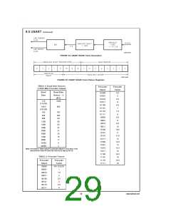
ENUI-USART Interrupt and Clock Source Register
(Address at 0BC)
STP2 STP78 ETDX SSEL XRCLK XTCLK
Bit 7
ERI
ETI
CHL1 = 0, CHL0 = 0
CHL1 = 0, CHL0 = 1
The frame contains eight data bits.
Bit 0
The frame contains seven data
bits.
STP2: This bit programs the number of Stop bits to be trans-
mitted. Read/Write, cleared on reset.
CHL1 = 1, CHL0 = 0
CHL1 = 1, CHL0 = 1
The frame contains nine data bits.
STP2 = 0
STP2 = 1
One Stop bit transmitted.
Two Stop bits transmitted.
Loopback Mode selected. Trans-
mitter output internally looped back
to receiver input. Nine bit framing
format is used.
STP78: This bit is set to program the last Stop bit to be 7/8th
of a bit in length. Read/Write, cleared on reset.
ERR: This bit is a global USART error flag which gets set if
any or a combination of the errors (DOE, FE, PE) occur.
Read only; it cannot be written by software, cleared on reset.
ETDX: TDX (USART Transmit Pin) is the alternate function
assigned to Port L pin L2; it is selected by setting ETDX bit.
To simulate line break generation, software should reset
ETDX bit and output logic zero to TDX pin through Port L
data and configuration registers. Read/Write, cleared on re-
set.
RBFL: This bit is set when the USART has received a com-
plete character and has copied it into the RBUF register. It is
automatically reset when software reads the character from
RBUF. Read only; it cannot be written by software, cleared
on reset.
SSEL: USART mode select. Read/Write, cleared on reset.
SSEL = 0
SSEL = 1
Asynchronous Mode.
Synchronous Mode.
TBMT: This bit is set when the USART transfers a byte of
data from the TBUF register into the TSFT register for trans-
mission. It is automatically reset when software writes into
the TBUF register. Read only, bit is set to “one” on reset; it
cannot be written by software.
XRCLK: This bit selects the clock source for the receiver
section. Read/Write, cleared on reset.
XRCLK = 0
The clock source is selected through the
PSR and BAUD registers.
ENUR-USART Receive Control and Status Register
(Address at 0BB)
XRCLK = 1
Signal on CKX (L1) pin is used as the clock.
XTCLK: This bit selects the clock source for the transmitter
section. Read/Write, cleared on reset.
DOE FE PE Reserved RBIT9 ATTN XMTG RCVG
(Note 14)
XTCLK = 0
The clock source is selected through the
PSR and BAUD registers.
Bit 7
Bit 0
Note 14: Bit is reserved for future use. User must set to zero.
XTCLK = 1
Signal on CKX (L1) pin is used as the clock.
DOE: Flags a Data Overrun Error. Read only, cleared on
ERI: This bit enables/disables interrupt from the receiver
read, cleared on reset.
section. Read/Write, cleared on reset.
DOE = 0
Indicates no Data Overrun Error has been de-
tected since the last time the ENUR register
was read.
ERI = 0
ERI = 1
Interrupt from the receiver is disabled.
Interrupt from the receiver is enabled.
www.national.com
26

 NSC [ National Semiconductor ]