to negative (high going low) for L Port bit 5, where bit 5 has
previously been enabled for an input interrupt. The program
would be as follows:
7.0 Power Saving Features (Continued)
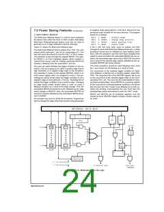
7.3 MULTI-INPUT WAKEUP
The Multi-Input Wakeup feature is used to return (wakeup)
the device from either the HALT or IDLE modes. Alternately
Multi-Input Wakeup/Interrupt feature may also be used to
generate up to 8 edge selectable external interrupts.
RBIT 5, WKEN
SBIT 5, WKEDG ; Change edge polarity
RBIT 5, WKPND ; Reset pending flag
; Disable MIWU
SBIT 5, WKEN
; Enable MIWU
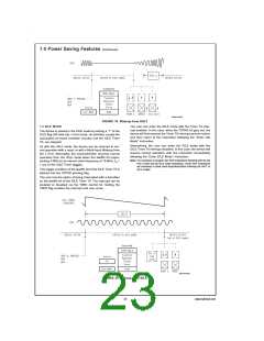
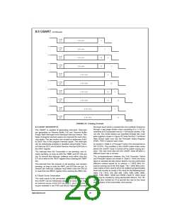
Figure 21 shows the Multi-Input Wakeup logic.
If the L port bits have been used as outputs and then
changed to inputs with Multi-Input Wakeup/Interrupt, a safety
procedure should also be followed to avoid wakeup condi-
tions. After the selected L port bits have been changed from
output to input but before the associated WKEN bits are en-
abled, the associated edge select bits in WKEDG should be
set or reset for the desired edge selects, followed by the as-
sociated WKPND bits being cleared.
The Multi-Input Wakeup feature utilizes the L Port. The user
selects which particular L port bit (or combination of L Port
bits) will cause the device to exit the HALT or IDLE modes.
The selection is done through the register WKEN. The regis-
ter WKEN is an 8-bit read/write register, which contains a
control bit for every L port bit. Setting a particular WKEN bit
enables a Wakeup from the associated L port pin.
This same procedure should be used following reset, since
the L port inputs are left floating as a result of reset.
The user can select whether the trigger condition on the se-
lected L Port pin is going to be either a positive edge (low to
high transition) or a negative edge (high to low transition).
This selection is made via the register WKEDG, which is an
8-bit control register with a bit assigned to each L Port pin.
Setting the control bit will select the trigger condition to be a
negative edge on that particular L Port pin. Resetting the bit
selects the trigger condition to be a positive edge. Changing
an edge select entails several steps in order to avoid a
Wakeup condition as a result of the edge change. First, the
associated WKEN bit should be reset, followed by the edge
select change in WKEDG. Next, the associated WKPND bit
should be cleared, followed by the associated WKEN bit be-
ing re-enabled.
The occurrence of the selected trigger condition for Multi-
Input Wakeup is latched into a pending register called WK-
PND. The respective bits of the WKPND register will be set
on the occurrence of the selected trigger edge on the corre-
sponding Port L pin. The user has the responsibility of clear-
ing these pending flags. Since WKPND is a pending register
for the occurrence of selected wakeup conditions, the device
will not enter the HALT mode if any Wakeup bit is both en-
abled and pending. Consequently, the user must clear the
pending flags before attempting to enter the HALT mode.
WKEN and WKEDG are all read/write registers, and are
cleared at reset. WKPND register contains random value af-
ter reset.
An example may serve to clarify this procedure. Suppose we
wish to change the edge select from positive (low going high)
DS101116-27
FIGURE 21. Multi-Input Wake Up Logic
www.national.com
24

 NSC [ National Semiconductor ]