Functional Description (Continued)
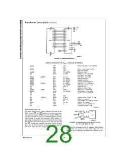
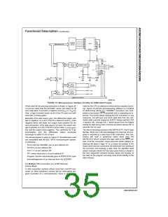
SAMPLE PROGRAM FOR Figure 16 ADC0801–MC6820 PIA INTERFACE
DS005671-A2
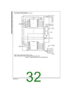
The following schematic and sample subroutine (DATA IN)
may be used to interface (up to) 8 ADC0801’s directly to the
MC6800 CPU. This scheme can easily be extended to allow
the interface of more converters. In this configuration the
converters are (arbitrarily) located at HEX address 5000 in
the MC6800 memory space. To save components, the clock
signal is derived from just one RC pair on the first converter.
This output drives the other A/Ds.
CPU, starts all the converters simultaneously and waits for
the interrupt signal. Upon receiving the interrupt, it reads the
converters (from HEX addresses 5000 through 5007) and
stores the data successively at (arbitrarily chosen) HEX ad-
dresses 0200 to 0207, before returning to the user’s pro-
gram. All CPU registers then recover the original data they
had before servicing DATA IN.
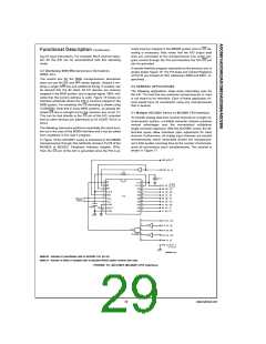
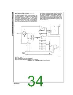
5.2 Auto-Zeroed Differential Transducer Amplifier
and A/D Converter
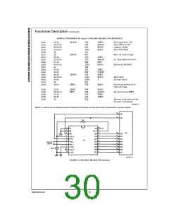
All the converters are started simultaneously with a STORE
instruction at HEX address 5000. Note that any other HEX
address of the form 5XXX will be decoded by the circuit, pull-
ing all the CS inputs low. This can easily be avoided by using
a more definitive address decoding scheme. All the inter-
rupts are ORed together to insure that all A/Ds have com-
pleted their conversion before the microprocessor is inter-
rupted.
The differential inputs of the ADC0801 series eliminate the
need to perform a differential to single ended conversion for
a differential transducer. Thus, one op amp can be elimi-
nated since the differential to single ended conversion is pro-
vided by the differential input of the ADC0801 series. In gen-
eral, a transducer preamp is required to take advantage of
the full A/D converter input dynamic range.
The subroutine, DATA IN, may be called from anywhere in
the user’s program. Once called, this routine initializes the
31
www.national.com

 NSC [ National Semiconductor ]