Nexperia
PMEG120G20ELR
120 V, 2 A Silicon Germanium (SiGe) rectifier
5. Pinning information
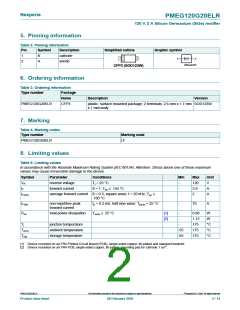
Table 2. Pinning information
Pin
1
Symbol
Description
cathode
Simplified outline
Graphic symbol
K
A
1
2
A
K
2
anode
006aab040
CFP3 (SOD123W)
6. Ordering information
Table 3. Ordering information
Type number
Package
Name
Description
Version
PMEG120G20ELR
CFP3
plastic, surface mounted package; 2 terminals; 2.6 mm x 1.7 mm SOD123W
x 1 mm body
7. Marking
Table 4. Marking codes
Type number
Marking code
PMEG120G20ELR
LF
8. Limiting values
Table 5. Limiting values
In accordance with the Absolute Maximum Rating System (IEC 60134). Attention: Stress above one of these maximum
values may cause irreversible damage to the device.
Symbol
VR
Parameter
Conditions
Min
Max
120
2.8
2
Unit
V
reverse voltage
forward current
Tj = 25 °C
-
-
-
IF
δ = 1; Tsp ≤ 155 °C
A
IF(AV)
average forward current δ = 0.5; square wave; f = 20 kHz; Tsp
160 °C
≤
A
IFSM
Ptot
non-repetitive peak
forward current
tp = 8.3 ms; half sine wave; Tj(init) = 25 °C
-
70
A
total power dissipation
Tamb ≤ 25 °C
[1]
[2]
-
0.68
1.15
175
175
175
W
-
W
Tj
junction temperature
ambient temperature
storage temperature
-
°C
°C
°C
Tamb
Tstg
-55
-65
[1] Device mounted on an FR4 Printed-Circuit Board (PCB), single-sided copper, tin-plated and standard footprint.
[2] Device mounted on an FR4 PCB, single-sided copper, tin-plated, mounting pad for cathode 1 cm2.
©
PMEG120G20ELR
All information provided in this document is subject to legal disclaimers.
Nexperia B.V. 2020. All rights reserved
Product data sheet
28 February 2020
2 / 14

 NEXPERIA [ Nexperia ]