CHAPTER 13 LCD CONTROLLER/DRIVER
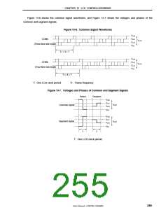
Figure 13-6 shows the common signal waveforms, and Figure 13-7 shows the voltages and phases of the
common and segment signals.
Figure 13-6. Common Signal Waveforms
VLC0
VLC1
VLC2
VSS
COMn
V
LCD
(Three-time slot mode)
TF = 3 × T
V
V
V
V
LC0
COMn
LC1
LC2
SS
V
LCD
(Four-time slot mode)
TF = 4 × T
T: One LCD clock period
TF: Frame frequency
Figure 13-7. Voltages and Phases of Common and Segment Signals
Select
Deselect
VLC0
V
LC1
V
V
LCD
Common signal
Segment signal
V
LC2
V
SS
V
V
V
LC0
LC1
LC2
LCD
V
SS
T
T
T: One LCD clock period
User’s Manual U15075EJ1V0UM00
255

 NEC [ NEC ]