NTC Proprietary
Level: Property
DDR3(L)-2Gb SDRAM
NT5CB(C)256M8JQ/NT5CB(C)128M16JR
CAS Latency
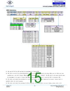
The CAS Latency is defined by MR0 (bit A2, A4~A6) as shown in the MR0 Definition figure. CAS Latency is the delay, in
clock cycles, between the internal Read command and the availability of the first bit of output data. DDR3(L) SDRAM does
not support any half clock latencies. The overall Read Latency (RL) is defined as Additive Latency (AL) + CAS Latency
(CL); RL = AL + CL.
Test Mode
The normal operating mode is selected by MR0 (bit7=0) and all other bits set to the desired values shown in the MR0
definition figure. Programming bit A7 to a ‘1’ places the DDR3(L) SDRAM into a test mode that is only used by the DRAM
manufacturer and should not be used. No operations or functionality is guaranteed if A7=1.
DLL Reset
The DLL Reset bit is self-clearing, meaning it returns back to the value of ‘0’ after the DLL reset function has been issued.
Once the DLL is enabled, a subsequent DLL Reset should be applied. Anytime the DLL reset function is used, tDLLK must
be met before any functions that require the DLL can be used (i.e. Read commands or ODT synchronous operations.)
Write Recovery
The programmed WR value MR0(bits A9, A10, and A11) is used for the auto precharge feature along with tRP to determine
tDAL WR (write recovery for auto-precharge)min in clock cycles is calculated by dividing tWR(ns) by tCK(ns) and rounding
up to the next integer: WRmin[cycles] = Roundup(tWR[ns]/tCK[ns]). The WR must be programmed to be equal or larger
than tWR (min).
Precharge PD DLL
MR0 (bit A12) is used to select the DLL usage during precharge power-down mode. When MR0 (A12=0), or ‘slow-exit’,
the DLL is frozen after entering precharge power-down (for potential power savings) and upon exit requires tXPDLL to be
met prior to the next valid command. When MR0 (A12=1), or ‘fast-exit’, the DLL is maintained after entering precharge
power-down and upon exiting power-down requires tXP to be met prior to the next valid command.
Version 1.4
05/2019
17
Nanya Technology Cooperation ©
All Rights Reserved.

 NANYA [ Nanya Technology Corporation. ]