NB675 –24V, HIGH CURRENT SYNCHRONOUS BUCK CONVERTER
OPERATION
PWM Operation
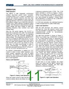
continuous-conduction-mode (CCM). The CCM
mode operation is shown in Figure 2 shown.
The NB675 is fully integrated synchronous
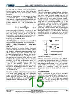
rectified step-down switch mode converter.
Constant-on-time (COT) control is employed to
provide fast transient response and easy loop
stabilization. At the beginning of each cycle, the
high-side MOSFET (HS-FET) is turned ON when
the feedback voltage (VFB) is below the reference
voltage (VREF), which indicates insufficient output
voltage. The ON period is determined by both the
output voltage and input voltage to make the
switching frequency fairy constant over input
voltage range.
When VFB is below VREF, HS-MOSFET is turned
on for a fixed interval which is determined by
one- shot on-timer as equation 1 shown. When
the HS-MOSFET is turned off, the LS-MOSFET
is turned on until next period.
In CCM mode operation, the switching frequency
is fairly constant and it is called PWM mode.
Light-Load Operation
With the load decrease, the inductor current
decrease too. Once the inductor current touch
zero, the operation is transition from continuous-
conduction-mode (CCM) to discontinuous-
conduction-mode (DCM).
After the ON period elapses, the HS-FET is
turned off, or becomes OFF state. It is turned ON
again when VFB drops below VREF. By repeating
operation this way, the converter regulates the
output voltage. The integrated low-side MOSFET
(LS-FET) is turned on when the HS-FET is in its
OFF state to minimize the conduction loss. There
will be a dead short between input and GND if
both HS-FET and LS-FET are turned on at the
same time. It’s called shoot-through. In order to
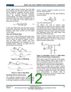
The light load operation is shown in Figure 3.
When VFB is below VREF, HS-MOSFET is turned
on for a fixed interval which is determined by
one- shot on-timer as equation 1 shown. When
the HS-MOSFET is turned off, the LS-MOSFET
is turned on until the inductor current reaches
zero. In DCM operation, the VFB does not reach
VREF when the inductor current is approaching
zero. The LS-FET driver turns into tri-state (high
Z) whenever the inductor current reaches zero. A
current modulator takes over the control of LS-
FET and limits the inductor current to less than -
1mA. Hence, the output capacitors discharge
slowly to GND through LS-FET. As a result, the
efficiency at light load condition is greatly
improved. At light load condition, the HS-FET is
not turned ON as frequently as at heavy load
condition. This is called skip mode.
avoid shoot-through,
internally generated between HS-FET off and LS-
FET on, or LS-FET off and HS-FET on.
a
dead-time (DT) is
An internal compensation is applied for COT
control to make a more stable operation even
when ceramic capacitors are used as output
capacitors, this internal compensation will then
improve the jitter performance without affect the
line or load regulation.
Heavy-Load Operation
At light load or no load condition, the output
drops very slowly and the NB675 reduces the
switching frequency naturally and then high
efficiency is achieved at light load.
Figure 2—Heavy Load Operation
Figure 3—Light Load Operation
When the output current is high and the inductor
current is always above zero amps, it is called
NB675 Rev. 1.0
1/14/2013
www.MonolithicPower.com
MPS Proprietary Information. Patent Protected. Unauthorized Photocopy and Duplication Prohibited.
© 2013 MPS. All Rights Reserved.
11

 MPS [ MONOLITHIC POWER SYSTEMS ]