MP4558 – 1A, 2MHz, 55V STEP-DOWN CONVERTER
APPLICATION INFORMATION
maximum switch current limit. Also, make sure
that the peak inductor current is below the
maximum switch current limit. Calculate the
inductance value with:
COMPONENT SELECTION
Setting the Output Voltage
Set the output voltage with a resistor divider
between the output voltage and the FB pin. The
voltage divider drops the output voltage down to
the feedback voltage by the ratio:
VOUT
VOUT
L1=
(1-
)
fs ΔIL
V
IN
R2
Where:
VFB=VOUT
R1+R2
VOUT is the output voltage,
VIN is the input voltage,
Thus the output voltage is:
R1+R2
R2
VOUT =VFB
fS is the switching frequency, and
∆IL is the peak-to-peak inductor ripple current.
For example, for R2 = 10kΩ, R1 can be
Choose an inductor that will not saturate under
the maximum inductor peak current. Calculate
the peak inductor current with:
determined by:
R112.5(VOUT 0.8)(k)
For example, for a 3.3V output voltage, R2 is
10kΩ, and R1 is 31.6kΩ.
VOUT
VOUT
ILP ILOAD
1
2 fS L1
V
IN
Inductor
Where ILOAD is the load current.
The inductor supplies constant current to the
output load while being driven by the switched
input voltage. A larger value inductor will result in
less ripple current that will lower the output ripple
voltage. However, a larger-valued inductor is
physically larger, has a higher series resistance,
or lower saturation current.
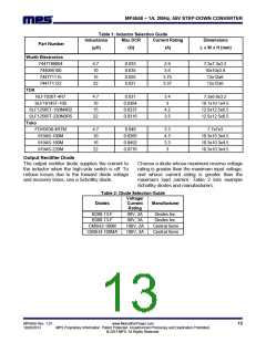
Table 1 lists a number of suitable inductors from
various manufacturers. The choice the inductor
style mainly depends on the price vs. size
requirements and any EMI requirement.
Generally, determine an appropriate inductance
value by selecting the peak-to-peak inductor
ripple current equal to approximately 30% of the
MP4558 Rev. 1.01
10/28/2013
www.MonolithicPower.com
MPS Proprietary Information. Patent Protected. Unauthorized Photocopy and Duplication Prohibited.
© 2013 MPS. All Rights Reserved.
12

 MPS [ MONOLITHIC POWER SYSTEMS ]