MP4558 – 1A, 2MHz, 55V STEP-DOWN CONVERTER
BLOCK DIAGRAM
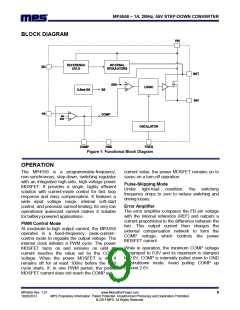
Figure 1: Functional Block Diagram
OPERATION
The MP4558 is a programmable-frequency,
non-synchronous, step-down, switching regulator
with an integrated high-side, high-voltage power
MOSFET. It provides a single, highly efficient
solution with current-mode control for fast loop
response and easy compensation. It features a
wide input voltage range, internal soft-start
control, and precision current limiting. Its very low
operational quiescent current makes it suitable
for battery-powered applications.
current value, the power MOSFET remains on to
saves on a turn-off operation.
Pulse-Skipping Mode
Under light-load condition, the switching
frequency drops to zero to reduce switching and
driving losses.
Error Amplifier
The error amplifier compares the FB pin voltage
with the internal reference (REF) and outputs a
current proportional to the difference between the
two. This output current then charges the
external compensation network to form the
COMP voltage, which controls the power
MOSFET current.
PWM Control Mode
At moderate-to-high output current, the MP4558
operates in a fixed-frequency, peak-current–
control mode to regulate the output voltage. The
internal clock initiates a PWM cycle. The power
MOSFET turns on and remains on until its
current reaches the value set by the COMP
voltage. When the power MOSFET is off, it
remains off for at least 100ns before the next
cycle starts. If, in one PWM period, the power
MOSFET current does not reach the COMP set
While in operation, the minimum COMP voltage
is clamped to 0.9V and its maximum is clamped
to 2.0V. COMP is internally pulled down to GND
in shutdown mode. Avoid pulling COMP up
beyond 2.6V.
MP4558 Rev. 1.01
10/28/2013
www.MonolithicPower.com
MPS Proprietary Information. Patent Protected. Unauthorized Photocopy and Duplication Prohibited.
© 2013 MPS. All Rights Reserved.
9

 MPS [ MONOLITHIC POWER SYSTEMS ]