Freescale Semiconductor, Inc.
Appendix: CGM Practical Aspects
and for the ‘acquisition’ mode:
1.675 – Fbus
10.795
⎛
⎞
⎠
2 ⋅ 109 ⋅ ζ2
π ⋅ R ⋅ C
415.61 ⋅ e⎝----------------------------- ⋅ R
Fc = ------------------------- = --------------------------------------------------------
2 ⋅ π ⋅ m
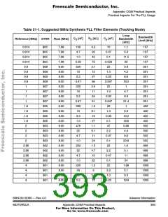
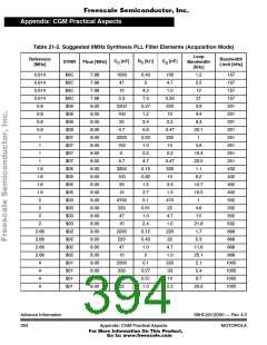
21.4.3.2 Particular Case of an 8MHz Synthesis
Assume that a desired value for the damping factor of the second order
system is close to 0.9 as this leads to a satisfactory transient response.
Then, derived from the equations above, Table 21-1 and Table 21-2
suggest sets of values corresponding to several loop bandwidth
possibilities in the case of an 8MHz synthesis for the two cases
mentioned above.
The filter components values are chosen from standard series (e.g. E12
for resistors). The operating voltage is assumed to be 5V (although there
is only a minor difference between 3V and 5V operation). The smoothing
capacitor Cp in parallel with R and C is set to be 1/10 of the value of
0
0
C . The reference frequencies mentioned in this table correspond to the
0
output of the fine granularity divider controlled by the REFDV register.
This means that the calculations are irrespective of the way the
reference frequency is generated (directly for the crystal oscillator or
after division). The target frequency value also has an influence on the
calculations of the filter components because the VCO gain is NOT
constant over its operating range.
The bandwidth limit corresponds to the so-called Gardner’s criteria. It
corresponds to the maximum value that can be chosen before the
continuous time approximation ceases to be justified. It is of course
advisable to stay far away from this limit.
Advance Information
392
68HC(9)12D60 — Rev 4.0
Appendix: CGM Practical Aspects
MOTOROLA
For More Information On This Product,
Go to: www.freescale.com

 MOTOROLA [ MOTOROLA ]