Freescale Semiconductor, Inc.
Appendix: CGM Practical Aspects
Practical Aspects For The PLL Usage
feature even in manual bandwidth control, offering then to the
application software the same flexibility for the clocking control as the
automatic mode.
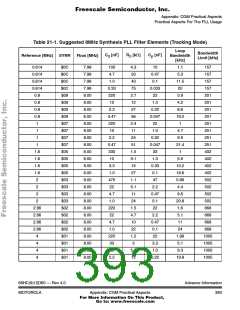
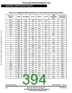
21.4.3 Filter Components Selection Guide
21.4.3.1 Equations Set
These equations can be used to select a set of filter components. Two
cases are considered:
1. The ‘tracking’ mode. This situation is reached normally when the
PLL operates in automatic bandwidth selection mode (AUTO=1 in
the PLLCR register).
2. The ‘acquisition’ mode. This situation is reached when the PLL
operates in manual bandwidth selection mode and forced
acquisition (AUTO=0, ACQ=0 in the PLLCR register).
In both equations, the power supply should be 5V. Start with the target
loop bandwidth as a function of the other parameters, but obviously,
nothing prevents the user from starting with the capacitor value for
example. Also, remember that the smoothing capacitor is always
assumed to be one tenth of the series capacitance value.
So with:
m:
R:
C:
the multiplying factor for the reference frequency (i.e. (synr+1))
the series resistance of the low pass filter in Ω
the series capacitance of the low pass filter in nF
: the target bus frequency expressed in MHz
the desired damping factor
F
bus
ζ:
F :
the desired loop bandwidth expressed in Hz
c
for the ‘tracking’ mode:
1.675 – Fbus
10.795
⎛
⎞
⎠
2 ⋅ 109 ⋅ ζ2
π ⋅ R ⋅ C
37.78 ⋅ e⎝----------------------------- ⋅ R
Fc = ------------------------- = -----------------------------------------------------
2 ⋅ π ⋅ m
68HC(9)12D60 — Rev 4.0
MOTOROLA
Advance Information
391
Appendix: CGM Practical Aspects
For More Information On This Product,
Go to: www.freescale.com

 MOTOROLA [ MOTOROLA ]