Freescale Semiconductor, Inc.
Electrical Specifications
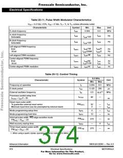
Table 20-11. Pulse Width Modulator Characteristics
V
= 5.0 Vdc ±10%, V = 0 Vdc, T = T to T , unless otherwise noted
SS A L H
DD
Characteristic
Symbol
Min
Max
Unit
f
E-clock frequency
0.004
8.0
MHz
eclk
A-clock frequency
Selectable
f
f
Hz
Hz
aclk
eclk
f
/128
eclk
B-clock frequency
Selectable
f
f
bclk
eclk
f
/128
/1M
eclk
Left-aligned PWM frequency
8-bit
16-bit
f
f
f
/2
/2
f
Hz
Hz
eclk
eclk
lpwm
f
/256M
eclk
eclk
r
f
/4K
f
Left-aligned PWM resolution
Hz
lpwm
eclk
eclk
Center-aligned PWM frequency
8-bit
16-bit
fcpwm
rcpwm
feclk/2M
feclk/512M
feclk
feclk
Hz
Hz
feclk/4K
feclk
Hz
Center-aligned PWM resolution
Table 20-12. Control Timing
8.0 MHz
Characteristic
Symbol
Unit
Min
Max
8.0
f
Frequency of operation
E-clock period
0.004
0.125
0.5
MHz
µs
o
t
250
cyc
(1)
f
External oscillator frequency
Processor control setup time
MHz
16.0
eo
t
82
—
PCSU
t
= t /2 + 20
ns
PCSU
cyc
Reset input pulse width
To guarantee external reset vector
Minimum input time (can be preempted by internal reset)
t
t
PW
t
32
2
—
—
cyc
RSTL
cyc
cyc
t
Mode programming setup time
4
—
—
MPS
t
Mode programming hold time
10
ns
ns
MPH
Interrupt pulse width, IRQ edge-sensitive mode
PW
t
270
—
—
4
IRQ
PW
= 2t + 20
IRQ
cyc
t
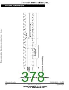
Wait recovery startup time
WRS
cyc
Timer input capture pulse width
PW
270
—
ns
TIM
PW
= 2t + 20
TIM
cyc
1. When using a quartz crystal, operation should be restricted to 8MHz.
Advance Information
374
68HC(9)12D60 — Rev 4.0
MOTOROLA
Electrical Specifications
For More Information On This Product,
Go to: www.freescale.com

 MOTOROLA [ MOTOROLA ]