Freescale Semiconductor, Inc.
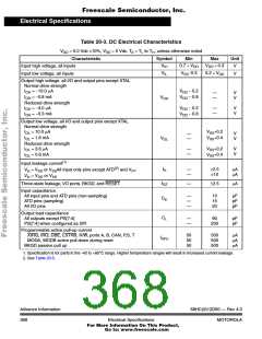
Electrical Specifications
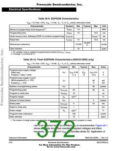
Table 20-9. EEPROM Characteristics
V
= 5.0 Vdc ±10%, V = 0 Vdc, T = T to T , unless otherwise noted
DD
SS
A
L
H
Characteristic
Symbol
Min
1.0
10
Typical
Max
Unit
MHz
ms
(1)
f
Minimum programming clock frequency
Programming time
PROG
t
10.5
PROG
t
t
+ 1
Clock recovery time, following STOP, to continue programming
Erase time
ms
CRSTOP
PROG
t
10
10,000
10
10.5
ms
ERASE
30,000
Write/erase endurance
Data retention
cycles
years
(2)
1. RC oscillator must be enabled if programming is desired and fSYS < fPROG
.
2. If average TH is below 85° C.
Table 20-10. Flash EEPROM Characteristics (68HC912D60 only)
V
= 5.0 Vdc ±10%, V = 0 Vdc, T = T to T , unless otherwise noted
DD
SS
A
L
H
Characteristic
Program/erase supply voltage:
Read only
Symbol
Min
Typical
Max
Units
V
V
−0.35
V
V
+0.5
DD
12.6
V
V
FP
DD
DD
Program / erase / verify
11.4
12
Program/erase supply current
Word program(V = 12V)
I
30
4
mA
mA
FP
FP
Erase(V = 12V)
FP
n
Number of programming pulses
Programming pulse
Program to verify time
Program margin
50
25
pulses
µs
PP
t
20
10
PPULSE
t
µs
VPROG
(1)
p
%
100
m
n
Number of erase pulses
Erase pulse
5
pulses
ms
EP
t
5
1
10
EPULSE
t
Erase to verify time
ms
VERASE
(1)
e
Erase margin
%
100
m
Program/erase endurance
Data retention
100
10
cycles
years
1. The number of margin pulses required is the same as the number of pulses used to program or erase.
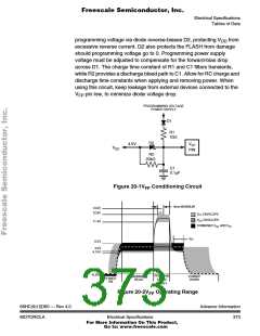
Use of an external circuit to condition V is recommended. Figure 20-1
FP
shows a simple circuit that maintains required voltages and filters
transients. V is pulled to V via Schottky diode D2. Application of
FP
DD
Advance Information
372
68HC(9)12D60 — Rev 4.0
MOTOROLA
Electrical Specifications
For More Information On This Product,
Go to: www.freescale.com

 MOTOROLA [ MOTOROLA ]