Freescale Semiconductor, Inc.
Motorola Interconnect Bus
The MCU (master) can take the bus at any time, with a start bit that
violates the rules of Manchester biphase encoding. Up to eight slave
devices may be addressed by the MI Bus. Other features of MI Bus
include message validation, error detection, and default value setting.
On the 68HC(9)12D60 the MI Bus module shares the same pins on port
S as the SCI0 module. Data is transmitted (or ‘pushed’) via the TxD0 pin,
and received (‘pulled’) via the RxD0 pin. While data is being pushed,
RxD0 will be disconnected from the receiver circuitry. The message
frame is handled automatically in hardware. The MCU register interface
is similar to that for the SCI.
16.3 Push-pull sequence
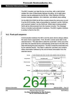
Communication between the MCU and the slave device always utilizes
the same frame organization. First, the MCU sends serial data to the
selected device. This data field is called the ‘push field’. At the end of the
push field, the selected device automatically sends back to the MCU the
data held during the push sequence. The MCU reads the serial data sent
by the selected device. This data is called the ‘pull field’ and contains
status information followed by the end-of-frame information from the
selected device.
Time slots
Push (biphase coded)
Pull (NRZ coded)
Push-pull function
TxD0 pin (true data)
MI Bus wire
1 0
0 1
0 1 2 3 4 5 6 7
Stop
Start
Push
D0 D1 D2 D3 D4 A0 A1 A2
sync sync
Pull
Bit fields
Start
NRZ
Data
Data
Address
End of frame
Push field
(driven by MCU)
Pull field
(driven by slave)
Message frame
Figure 16-1. MI Bus timing
Advance Information
264
68HC(9)12D60 — Rev 4.0
MOTOROLA
Motorola Interconnect Bus
For More Information On This Product,
Go to: www.freescale.com

 MOTOROLA [ MOTOROLA ]