Freescale Semiconductor, Inc.
Enhanced Capture Timer
0 = Queue Mode of Input Capture is enabled.
The main timer value is memorized in the IC register by a valid
input pin transition.
With a new occurrence of a capture, the value of the IC register
will be transferred to its holding register and the IC register
memorizes the new timer value.
1 = Latch Mode is enabled. Latching function occurs when
modulus down-counter reaches zero or a zero is written into
the count register MCCNT (see Buffered IC Channels).
With a latching event the contents of IC registers and 8-bit
pulse accumulators are transferred to their holding registers.
8-bit pulse accumulators are cleared.
BIT 7
6
0
0
5
0
0
4
0
0
3
0
0
2
0
0
1
TCBYP
0
BIT 0
0
0
0
0
RESET:
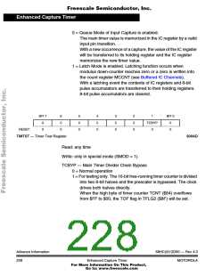
TIMTST — Timer Test Register
$00AD
Read: any time
Write: only in special mode (SMOD = 1).
TCBYP — Main Timer Divider Chain Bypass
0 = Normal operation
1 = For testing only. The 16-bit free-running timer counter is divided
into two 8-bit halves and the prescaler is bypassed. The clock
drives both halves directly.
When the high byte of timer counter TCNT ($84) overflows
from $FF to $00, the TOF flag in TFLG2 ($8F) will be set.
Advance Information
228
68HC(9)12D60 — Rev 4.0
Enhanced Capture Timer
MOTOROLA
For More Information On This Product,
Go to: www.freescale.com

 MOTOROLA [ MOTOROLA ]